Tag Archives: mower pto shaft

China supplier Tractor Mower with Pto Drive Shaft Finishing Mower with Hot selling

Product Description

Specifications:;

hot selling farm tractor PTO finishing mower for Europe
Style:; FM-120 -150 -180
Change color upon request
Well-known in Europe
3 point linkage
Graphite casting iron gearbox
Tractor power required:; 18-35hp

Product Attribute
1.; Transmission:; V belt transmission,; more reliable.;
2.; Graphite gearbox is made of casting iron.; Material performance is better.; Not easy broken.;
3.;3 pieces of blades are working meanwhile,; expanding the cutting width.;
4.; Blade shaft seat is made of casting iron.; More reliable and strong.;
5.; Rear-discharge and side-discharge can be selectable for you.;
6.; The wheel is clad in rubber,; more stable and wear-resistant.;
7.;Mainly for cutting grass in the flat area,; and smaller bushes or weeds below half a meter.;
8.; Mowing height can be adjusted.;

Functions:;
Detailed Product Description on Finishing Mower
Uses:;
Perfect for use when presentation is essential,; ideal for work around golf courses,; sporting fields,; parklands,; camping grounds,; schools,; homesteads and roadsides,; rear discharge for normal use or side discharge option for use in areas where the cuttings need to be thrown clear? Like under orchards.;

Features:;
Rear or side discharge options,; 4 independent height adjustable castor wheels allow the mower to contour over uneven surfaces to provide an even finish,; 3 high strength cutting blades for a more precision finish,; floating top hitch to increase surface contouring.;

Advantages of our company—HangZhou Lefa

1.; Specializing in manufacturing and selling the farm machine more than 11 years.;

2.; “Lefa” produce in China and France.;

3.; With CE certificate.;.;

4.; With the strict quality control and best service for customers.;

5.; We can provide excellent and rapid after-sales service.;

6.; Our aim:; Win-win.;

7.; We can design and produce machines according to customer’s needs.;

8.; We developed dozens of Japanese tractors parts,; we can deliver the parts with machine together.;
Co-operation Policy:;

1.; Sample Policy:; You can test the quality of our sample firstly before you purchase them in mass
Quantity.;

2.; Payment Way:; T/T,; L/C,; Western Union,; D/P.;

3.; Delivery Date:; 10-30 days after deposit paid.; It depend on your order quantity.;

4.; Shipping Way:; By Sea or By Air.;

5.; After Service:; 12 months guarantee of the main parts,; we will send the guarantee parts together with the machine in your next order or we can send them by air express if you need them urgently.;

Our Purpose:;
Quality first,; best service,; win-win!

We sincerely welcome customers abroad to visit us to discuss cooperation and seek common development.; We believe our company is your most reliable partner and friend!

Model Dimension(mm); PTO (rpm); No of Blades  Power Required Packing Size(mm);
FM-120 1260*1200*650 540 2 or 3 18-25hp 1400*760*2200
FM-150 1570*1200*650 540 2 or 3 20-30hp 1700*860*2200
FM-180 1860*1350*650 540 2 or 3 20-35hp 2000*1100*2200
FM-100 1100*1100*700 540 2 or 3 16-25HP 1200*1150*2200

How to find quality agricultural accessories

Agricultural accessories are very important in tractors, harvesters and more. If you’re in the market for new agricultural parts, you may want to choose steel. Steel is the best choice for agricultural equipment because it is corrosion-resistant, durable and cost-effective. However, you also need to consider other materials such as aluminum and plastic. Here are some tips for finding quality agricultural parts. Hope this information is helpful to you.
agriculturalparts

Steel is the best metal for farm equipment

Steel has many benefits, but why is it the best metal for farm equipment? Steel is lightweight and corrosion-resistant, making it ideal for agricultural applications. It has many other benefits, including resistance to chemical pesticides. Stainless steel is highly recyclable and has antimicrobial properties. It retains its integrity even when exposed to outdoor temperatures. It also has the added advantage of being able to withstand the rigors of agricultural life.
Agricultural machinery made of steel is also known for its durability. Agricultural equipment made of steel is known for its durability and ease of maintenance. Steel has a smooth surface that is easy to clean, which is especially important in dairy farming, where smooth surfaces are critical to maintaining the quality of raw milk. For those who need metal parts for agricultural equipment, Guocai is the best source. Their team of experts can help you find the right metal for your agricultural equipment and provide you with a complete metal fabrication service.
Agricultural equipment made of steel is often heavy, so finding ways to reduce weight is important. Aluminum alloys are a good choice because they are lighter than steel and suitable for dusty environments. Also, since they are more durable than steel, aluminum alloys are ideal for moving parts of agricultural machinery. Aluminum also has high tensile strength, making it ideal for dusty environments.
In addition to being sturdy and durable, the steel structure is low maintenance and ideal for storing agricultural equipment. They can hold multiple pieces of equipment and have an open interior, which means you can easily store other equipment inside. Due to the high technical content of farming, you may need to invest in a flexible steel building. To help you achieve these goals, CZPT offers agricultural buildings that are ideal for storing a variety of items.
agriculturalparts

Corrosion Resistance

Stainless steel is recommended for use in corrosive environments. Stainless steel is an alloy of iron, chromium, silicon and carbon. It also contains significant amounts of nickel and molybdenum. All stainless steels contain at least 10 percent chromium. This alloy has excellent corrosion resistance and strength. There are certain applications where stainless steel is more suitable than traditional steel:
Agricultural components are often corroded due to their high carbon content. Depending on the metal and the environment, the resulting corrosion products may have different properties. The initial step of etching may result in the formation of ions. This ion then oxidizes further and forms oxides or other mixed valence compounds. The presence of dense oxide layers prevents further corrosion, but these layers are also porous. Therefore, the corrosion process can continue.
When selecting biomedical materials, researchers should test the corrosion resistance of materials. Normally, the pH of fluids in the human body is 7.4. However, during surgery, the pH of fluids in the body may change to a range of 5.5 to 7.8. After a few days, this pH will return to normal. Titanium and 316L stainless steel have better corrosion resistance than cobalt-based alloys.

Durable

Steel was first used in farm implements by John Deere, who introduced the steel plow in 1837. Steel makes plows more efficient and faster. Today, steel remains the most durable material used for farm implements, depending on the application. For example, heavy equipment is mainly made of steel. The tractor has a structural steel housing and a strong steel frame for corrosion resistance in agricultural environments. This is an advantage for farmers and agronomists.
Cost-effective

Farmers often purchase farm machinery directly, rather than renting or leasing accessories. This gives them ownership of the machine and is often more cost-effective in the long run. Also, buying equipment outright helps them establish equity. Farm machinery is expensive, so farmers are usually more willing to buy them. But leasing or renting parts is also a cost-effective option. Read on to learn more. What are the benefits of renting agricultural parts?
Agricultural equipment is made from many different materials and is often manufactured using an open or closed mold process. The use of thermoset composites is not uncommon, although reinforced thermoplastics are starting to gain traction in specific applications. For example, aerospace-grade prepregs are commonly used for cantilevers on sprayers. Alternatively, steel and aluminum arms are used for agricultural equipment, but require support structures to provide the required stability.
agriculturalparts

Easy to maintain

Many modern agricultural machines contain computer systems, sensors and other technologies that make them difficult to maintain without the help of experts. While not an impossible task, it does require specific diagnostic software and tools that most manufacturers don’t offer to the public. As a result, many farmers do not have access to the tools and diagnostic software needed to repair equipment and must take it to a licensed dealer for repairs.
Fortunately, there are some solutions to this problem. A recent executive order from President Biden, who oversees the federal government, calls for more competition in the economy. His executive order calls on the FTC to limit unfair trade practices and promote U.S. economic growth. One of the recommendations is that consumers have the right to repair farm equipment. Many agricultural products are affected by the new laws as they become more integrated and less competitive, meaning farmers and ranchers are forced to pay more for their produce.

China supplier Tractor Mower with Pto Drive Shaft Finishing Mower     with Hot sellingChina supplier Tractor Mower with Pto Drive Shaft Finishing Mower     with Hot selling

China Hot selling Farming Equipment with Pto Drive Shaft Rotary Toppers Mower wholesaler

Product Description

MODEL TM110 TM140 TM160 TM170
Structure Weight 175kg 205kg 215kg 225kg
Cutting Width 1060mm 1360mm 1560mm 1760mm
Tractor HP 18-25hp 20-35hp 25-40hp 30-50hp

Topper Mower is perfect for topping a variety of grasses ideal for pasture and paddock areas.

Fully adjustable skids for regulating cutting height and with 3 point linkage, suitable for most compact or medium sized tractors.
Medium duty CZPT with re-enforced frame, designed with safety plate or chains you can choose.
The sturdy steel structure gives both strength and reliability to our CZPT Mowers.
Can be used on smallholdings for paddock areas with grazing horses, sheep or alpacas.
HangZhou Qianyi Machinery Technology Co.,Ltd existing staff 50 people, in 2571 passed the ISO9001 quality system certification and passed CE certification.

Accumulated after years of development, we have many advanced equipment, like Germany fast Trulaser3030 laser cutting ,machine, CNC punch press TruPunch1000, CNC shearing machine, CNC lathe, bending machine, seam welding machine and more than 1 formula 1-160-1 high-end mechanical production equipment.

We provide good design, to help customers reduce costs of development and improve production efficiency. With complete testing equipment, strict quality control and abundant technical force, our machines are mainly exported to European, North American and Southeast Asian countries.

All of our machines are with 1 year warranty. We often insist on 1 principle”Better quality!Better service!Better price!”

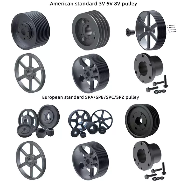
Overview of Different Types of Pulleys

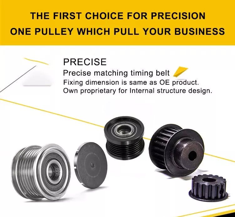
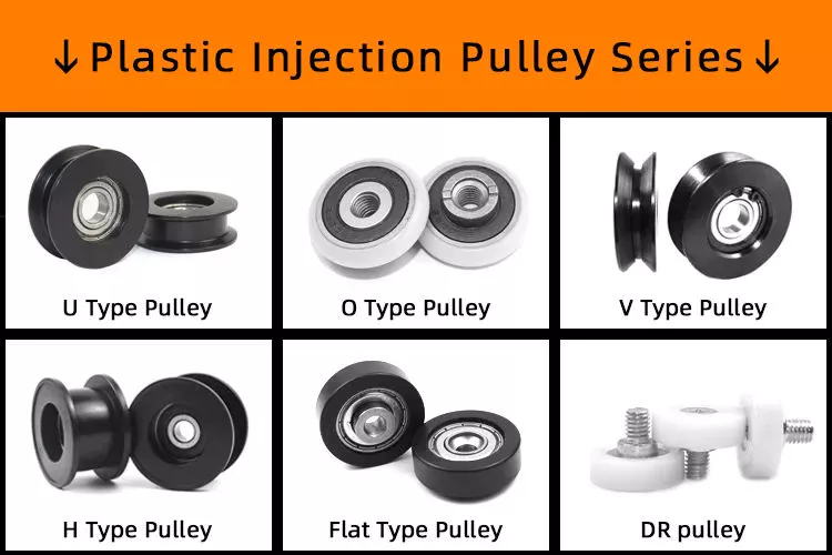
A pulley is a wheel mounted on a shaft or shaft. Its purpose is to facilitate the movement or change of direction of the cable or taut rope, and to transmit power between the cable and the shaft. Pulleys are typically used for lifting, winding or forklift applications. If you are building your own pulley system, the following design and installation considerations should be followed. This article will give you an overview of the different types of pulleys.
pulley

Pulley System Mechanics

There are many different ways to utilize the mechanism of the pulley system. The most basic pulley system consists of a fixed wheel and a support frame. Both components are connected by ropes or cables used to support the load. A pulley system is effective when the force required to lift the load is less than the weight of the object being lifted.
One way to use a pulley system is to suspend a block with a mass of 0.80 kg on a fixed pulley. Then another person can hang a bucket weighing up to 40kg. The weight of the bucket is transferred to the fixed pulley. The rope is attached to the pulley by a loop or sling. The rope will spin and pull on the barrel or block.
The pulley system is also an important tool for lifting heavy objects. Pulleys are often used in construction equipment to make lifting heavy objects easier. Gun tackles, yard tackles, and stationary tackle systems are common examples of these devices. They use the mechanical advantage of the design to guide the force that lifts the object. If you want to learn more about pulley systems, visit Vedantu. This website will provide you with a full description of the mechanism and its application.

Types of pulleys

Many different types of pulleys are used to lift heavy objects. They change the direction of the force and are an integral part of the cable system. Therefore, pulleys can move large and heavy objects more easily. However, before buying a pulley, you should have an idea of ​​the benefits it brings. Below are some of the most common uses for pulleys.
Conical Pulley: Consists of several small conical pulleys connected to each other. The larger base of 1 pulley is used to guide the force. Round pulleys are used in the same way as step pulleys. They are widely used in industry and can be purchased at any hardware store. Pulleys are a huge investment, and the benefits they provide far outweigh the cost.
Movable Pulls: These are similar to their names, but work by allowing objects to move with the pull. Their movable parts are attached to the object to be lifted. They are also ideal for lifting heavy loads and can be found in utility elevators and construction cranes. They are also used in many other industries. They can also be made of wood, plastic or metal. The type of pulley you use depends on its intended use.

Mechanical Advantages of Pulley Systems

A pulley system is a simple machine that reduces the effort required to lift heavy loads. This mechanical advantage is proportional to the number of loops. For example, if you have a single rope loop, you must apply equal force to lift the weight. When you add another rope loop, you can lift heavier weights just by applying the same force. Therefore, a pulley system is an excellent way to use gravity to your advantage.
Mechanical advantage is a measure of the effectiveness of a pulley system. This ratio of force to work is called the mechanical advantage. In other words, if the rope system has a large mechanical advantage, it means that it requires less force to lift heavier loads. This advantage is usually measured in kilograms and is the same for all pulley systems. In general, the greater the mechanical advantage, the less effort is required to lift the load.
The mechanical advantage of a pulley system is that a single movable pulley requires half the force to lift an object than a single fixed pulley. Assuming frictionless bearings, the MA of a single pulley system is 2, similar to the MA of a single lever. A single pulley travels twice as much as it takes to move heavy objects manually.
pulley

Considerations when designing and installing a pulley system

The capacity of the pulley depends on the type and diameter of the cable. Besides its diameter, its sheath should also support it well. The basic function of the pulley is also important. However, most people tend to ignore the pulley selection process, resulting in ineffective load-pull capabilities. To avoid such problems, different parameters must be carefully considered during design and installation.
During the design and installation of the pulley system, the ratio of the cable diameter to the largest pulley diameter must be considered. Those who work in the industrial sector will have an idea of ​​this ratio. The greater the D:d ratio, the greater the capacity of the cable to withstand the load. The best way to ensure secure design is to take the right information and use it to design a system that is both robust and secure.
When designing a pulley system, it is important to remember that the pulley needs to have enough power to operate safely. In addition to horsepower, the belt should have sufficient elongation to absorb shock loads. If the elongation of the belt is very small, it is very likely that the teeth will be sheared or broken, causing serious damage to the system. Extensive belt sag should be compensated for by offsetting the driven pulley. Finally, the frame supporting the pulley should be rigid. Otherwise, the non-rigid frame will cause center distance and tooth skipping changes.

Add more pulleys to the system

Adding more pulleys to the spool might have some effect. The friction between the rope and the pulley increases with the number of pulleys, which in practice limits the number of spools. The best solution is to combine the pulleys into 1 housing. If the load is small enough, adding a few pulleys probably won’t make a difference.
Using multiple pulleys allows a single load to be lifted with half the force required. The longer the rope, the greater the mechanical advantage. In fact, a spool can withstand a load of 100 N. Additionally, adding more pulleys quadrupled the mechanical advantage. In this case, a single 100 N load would require a force of 25 Newtons.
When the rope is used, it stretches as the weight of the object increases. This will make the rope longer, increasing its length and increasing the distance over which the load can be lifted. Eventually, the rope will break and the lifted object will fall. Then you will have to buy a new rope. It may seem like an expensive proposition, but it pays off in the long run.

cast iron pulley

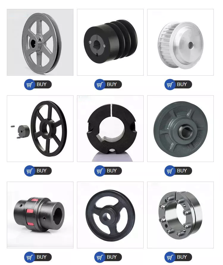
Cast iron pulleys are the most popular choice among industrial users. They are made of solid cast iron and usually cost very little. Their rims are held in place by a mesh that extends from a central boss. They also have spokes and arms that hold them in place. These pulleys are ideal for a variety of applications including fan belts, compressors and conveyors.
V-groove drive pulleys are ideal for general purpose pulleys. It has an inner diameter of 1 inch and is commonly used in feeders and ventilation curtain systems. Its steel straps prevent rust and ensure it meets or exceeds industry standards. 3-1/2″ cast iron pulleys are also available. In addition to the V-groove drive pulley, there are similar pulleys for power transmission. The V-groove drive pulley is powder coated for added durability.
The cross section of the arm is elliptical, with the long axis twice as long as the short axis. The radius of the arm is equal to the diameter of the pulley. The thickness of the arm is a key factor to consider when purchasing a pulley. If you’re not sure which material you need, you can always consider wooden or steel pulleys. They are lighter and have a higher coefficient of friction than metal pulleys.
pulley

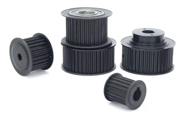
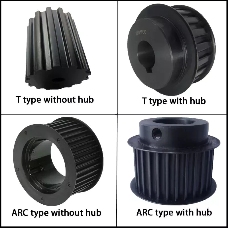
timing pulley

Plastic timing pulleys have many advantages over steel timing pulleys. On the 1 hand, they are lightweight and corrosion resistant, making them ideal for applications that do not require high torque and tensile strength. Another benefit is their resistance to high temperatures. Plastic timing pulleys are ideal for applications involving flammable gases, solvents or particles. They can last for many years. For more information on the different types of plastic timing pulleys.
Vertical shaft drives require flanged timing pulleys. For large span drives, at least 1 of these pulleys must be flanged. The flange provides a secure connection to the shaft and prevents ratcheting of the timing belt. Finally, HTD timing belt teeth prevent timing belt ratcheting. These teeth need a large enough space to be seated. However, they can also cause a backlash. These pulleys are not suitable for applications where positional accuracy is critical.
Timing belt systems are designed to avoid such problems. The drive shaft and the driven shaft are aligned with each other. The pulleys are located on different planes and are connected by pitch lines. The pitch line of the timing pulley coincides with the pitch line of the belt. These pulleys are also easier to implement and maintain. It is better to use a synchronous system because the resulting gear system emits less noise than other systems.

China Hot selling Farming Equipment with Pto Drive Shaft Rotary Toppers Mower     wholesaler China Hot selling Farming Equipment with Pto Drive Shaft Rotary Toppers Mower     wholesaler

China Best Sales Flail Mower with Double Blades for 3 Point Link Pto Shaft Tractor near me supplier

Product Description

Flail Mower

    1. Transmission: By sturdy toothed belts.
    2. Gearbox is made of gravity casting iron. Material performance is better. Not easy broken.
    3. With adjustable rear roller, the mowing height can be adjusted.
    4. The structure is firm and stable.
    5.  High welding processes
    6.  With front protection, it can prevent splashing.
    7. Y shape blades, hammer and vertical blades for grass. With double blades.
    8. Cat. I universal three-point hitch cardan shaft.


Model

EFD-95 EFD-105 EFD-115 EFD-125 EFD-135
Dimension(mm) 1040×700×520 1140×700×520 1240*700*520 1340×700×520 1440×700×520
Weight(Kg) 130 KG 145Kg 155KG 170Kg 175Kg
Cutting Width 950mm 1050mm 1150mm 1250mm 1350mm
 PTO Input Speed 540r/min 540r/min 540r/min 540r/min 540r/min
Y shape blades 60 72 78 84 84
Power Required 16-20HP 20-25HP 20-30HP 20-30HP 20-30HP
3 point linkage  Cat.1 Cat.1  Cat.1 Cat.1 Cat.1
Packing size(mm) 1150×750×550 1250×750×550 1350*750*550 1450×750×550 1550×750×550

Company Profile

HangZhou CZPT Industry & Trade Co., Ltd., is a professional manufacturer and exporter of whole set of agriculture machines and garden tools. Our company was established since 2003 with Hanma Industry Company.

Our main products include rotovator, flail mower, finishing mower, CZPT mower, wood chipper, plow, cultivator, potato harvester/ planter and Japanese tractor parts, etc. Due to our super International quality standard and rapid & excellent after-sales service, CZPT machines are greatly popular in various markets around the world, and already reached to Europe, North America, South America, Australia, almost covers 80 countries in World.

LEFA always believe that we will take better farming life to you by top-quality laser cutting machine & CNC bending machine & professional paint-spraying & strong welding.

PROFESSIONAL PRODUCTION:

1.Professional team with rich experience

2.Powerful factory strength with CE certification

3.Best after-sales service


Packing & Shipping

Packaging Detail: Iron pallet or wooden cases
Delivery Detail: By sea or By air

1. Waterproof packing with the international export standard by 20ft, 40ftcontainer.
Wooden Case or Iron Pallet.
2. The whole set of machines size are large as normal, so we will use Waterproof materials to pack
all of them. The motor, gear box or other easily damaged parts, we will put them into box. 

We have a professional shipping department, they will try their best to save your container quantity.

Machine videos in YOUTOBE

          EFDL SIDE MOWERS

         EFGL SIDE MOWERS

          FM FINISHING MOWERS

        TM CZPT MOWERS

            RT ROTARY TILLERS

https://youtu.be/d3H1-yXUImc                                 AP-90 POTATO HARVESTER

https://youtu.be/AAkgnV_bY80                        LF-PT32 POTATO PLANTER

https://youtu.be/66geQQOUTLY                        wood chipper BX-42

https://youtu.be/iIVOwCTCl_c                       HAY BALER

FAQ:
Q1. How to buy 3 point rotary tiller?
Inquiry ———> Quotation ——–>Price reasonable ——->Check with specification —–>Proforma Invoice sent ————>Payment made ——-> Producing the items ——->Product shipment ———–> Customer confirm

Q2.How long is the delivery date for agriculture machinery cultivator?
A:In general, we can ship the goods within 30-45 days after receiving your payment. Of course, it also depends on your quantity.

Q3. How can I get to your factory to buy tractor cultivator?
A:We are located in HangZhou, only 1 hour’s distance to ZheJiang or HangZhou. You can fly to ZheJiang /HangZhou/HangZhou Airport , the transportation is very convenient

Q4.Do you have stock for rotary tiller?
A:In general, we have some stock, while if you need a bulk order, we still need time to produce it. Of course, we will inform all details you before your payment.

Q5: What’s your main products?
A: Our products are covered almost all farm machines and Japanese tractors parts, we can meet your any demands.

Q6. What is your terms of payment?
A: T/T, L/C, Paypal, Western Union

How to Replace a Bearing

If you want to select a bearing for a specific application, you should know a few basics. This article will give you an overview of ball, angular contact, and sliding-contact bearings. You can choose a bearing according to the application based on the characteristics of its material and preload. If you are not sure how to choose a bearing, try experimenting with it. The next step is to understand the Z-axis, which is the axes along which the bearing moves.

Z axis

When it comes to replacing your Z axis bearing, there are several things you must know. First, you need to make sure that the bearings are seated correctly. Then, you should check the tension and rotation of each one. To ensure that both bearings are equally tensioned, you should flex the Core to the desired angle. This will keep the Z axis perpendicular to the work surface. To do this, first remove the Z axis bearing from its housing and insert it into the Z axis motor plate. Next, insert the flanged bearing into the Z axis motor plate and secure it with 2 M5x8mm button head cap screws.
Make sure that the bearing plate and the Z Coupler part are flush and have equal spacing. The spacing between the 2 parts is important, as too much spacing will cause the leadscrew to become tight. The screws should be very loose, with the exception of the ones that engage the nylocks. After installing the bearing, the next step is to start the Z axis. Once this is done, you’ll be able to move it around with a stepper.

Angular contact

bearing
Ball bearings are made with angular contacts that result in an angle between the bearing’s races. While the axial load moves in 1 direction through the bearing, the radial load follows a curved path, tending to separate the races axially. In order to minimize this frictional effect, angular contact bearings are designed with the same contact angle on the inner and outer races. The contact angle must be chosen to match the relative proportions of the axial and radial loads. Generally, a larger contact angle supports a higher axial load, while reducing radial load.
Ball bearings are the most common type of angular contact bearings. Angular contact ball bearings are used in many applications, but their primary purpose is in the spindle of a machine tool. These bearings are suitable for high-speed, precision rotation. Their radial load capacity is proportional to the angular contact angle, so larger contact angles tend to enlarge with speed. Angular contact ball bearings are available in single and double-row configurations.
Angular contact ball bearings are a great choice for applications that involve axial loads and complex shapes. These bearings have raceways on the inner and outer rings and mutual displacement along the axial axis. Their axial load bearing capacity increases as the contact Angle a rises. Angular contact ball bearings can withstand loads up to 5 times their initial weight! For those who are new to bearings, there are many resources online dedicated to the subject.
Despite their complexity, angular contact ball bearings are highly versatile and can be used in a wide range of applications. Their angular contact enables them to withstand moderate radial and thrust loads. Unlike some other bearings, angular contact ball bearings can be positioned in tandem to reduce friction. They also feature a preload mechanism that removes excess play while the bearing is in use.
Angular contact ball bearings are made with different lubricants and cage materials. Standard cages for angular contact ball bearings correspond to Table 1. Some are machined synthetic resins while others are molded polyamide. These cage materials are used to further enhance the bearing’s axial load capacity. Further, angular contact ball bearings can withstand high speeds and radial loads. Compared to radial contact ball bearings, angular contact ball bearings offer the greatest flexibility.

Ball bearings

bearing
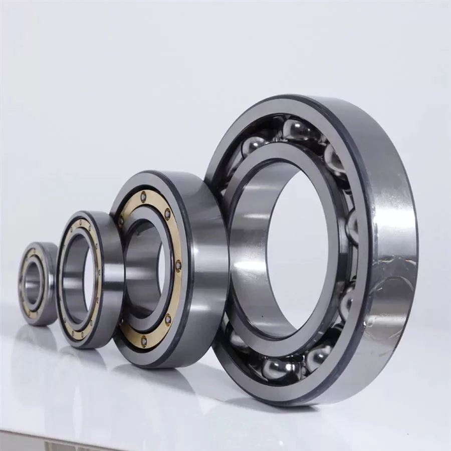
Ball bearings are circular structures with 2 separate rings. The smaller ring is mounted on a shaft. The inner ring has a groove on the outer diameter that acts as a path for the balls. Both the inner and outer ring surfaces are finished with very high precision and tolerance. The outer ring is the circular structure with the rolling elements. These elements can take many forms. The inner and outer races are generally made of steel or ceramic.
Silicon nitride ceramic balls have good corrosion resistance and lightweight, but are more expensive than aluminum oxide balls. They also exhibit an insulating effect and are self-lubricating. Silicon nitride is also suitable for high-temperature environments. However, this type of material has the disadvantage of wearing out rapidly and is prone to cracking and shattering, as is the case with bearing steel and glass. It’s also less resistant to heat than aluminum oxide, so it’s best to buy aluminum nitride or ceramic ball bearings for applications that are subjected to extremely high temperatures.
Another type of ball bearings is the thrust bearing. It has a special design that accommodates forces in both axial and radial directions. It is also called a bidirectional bearing because its races are side-by-side. Axial ball bearings use a side-by-side design, and axial balls are used when the loads are transmitted through the wheel. However, they have poor axial support and are prone to separating during heavy radial loads.
The basic idea behind ball bearings is to reduce friction. By reducing friction, you’ll be able to transfer more energy, have less erosion, and improve the life of your machine. With today’s advances in technology, ball bearings can perform better than ever before. From iron to steel to plastics, the materials used in bearings have improved dramatically. Bearings may also incorporate an electromagnetic field. So, it’s best to select the right 1 for your machine.
The life expectancy of ball bearings depends on many factors, including the operating speed, lubrication, and temperature. A single million-rpm ball bearing can handle between 1 and 5 million rotations. As long as its surface contact area is as small as possible, it’s likely to be serviceable for at least 1 million rotations. However, the average lifespan of ball bearings depends on the application and operating conditions. Fortunately, most bearings can handle a million or more rotations before they start showing signs of fatigue.

Sliding-contact bearings

bearing
The basic principle behind sliding-contact bearings is that 2 surfaces move in contact with 1 another. This type of bearing works best in situations where the surfaces are made of dissimilar materials. For instance, a steel shaft shouldn’t run in a bronze-lined bore, or vice versa. Instead, 1 element should be harder than the other, since wear would concentrate in that area. In addition, abrasive particles tend to force themselves into the softer surface, causing a groove to wear in that part.
Sliding-contact bearings have low coefficients of friction and are commonly used in low-speed applications. Unlike ball and roller bearings, sliding contact bearings have to be lubricated on both sides of the contacting surfaces to minimize wear and tear. Sliding-contact bearings generally are made of ceramics, brass, and polymers. Because of their lower friction, they are less accurate than rolling-element bearings.
Sliding-contact bearings are also known as plain or sleeve bearings. They have a sliding motion between their 2 surfaces, which is reduced by lubrication. This type of bearing is often used in rotary applications and as guide mechanisms. In addition to providing sliding action, sliding-contact bearings are self-lubricating and have high load-carrying capacities. They are typically available in 2 different types: plain bearings and thrust bearings.
Sliding-contact linear bearing systems consist of a moving structure (called the carriage or slide) and the surfaces on which the 2 elements slide. The surfaces on which the bearing and journal move are called rails, ways, or guides. A bore hole is a complex geometry, and a minimum oil film thickness h0 is usually used at the line of centers. It is possible to have a sliding-contact bearing in a pillow block.
Because these bearings are porous, they can absorb 15 to 30% of the lubrication oil. This material is commonly used in automobile and machine tools. Many non-metallic materials are used as bearings. One example is rubber, which offers excellent shock absorbency and embeddability. While rubber has poor strength and thermal conductivity, it is commonly used in deep-well pumps and centrifugal pumps. This material has high impact strength, but is not as rigid as steel.

China Best Sales Flail Mower with Double Blades for 3 Point Link Pto Shaft Tractor     near me supplier China Best Sales Flail Mower with Double Blades for 3 Point Link Pto Shaft Tractor     near me supplier

China manufacturer 20-30HP Compact Tractor Flail Mower with Pto Shaft with Hot selling

Product Description

Flail Mower

    1. Transmission: By sturdy toothed belts.
    2. Gearbox is made of gravity casting iron. Material performance is better. Not easy broken.
    3. With adjustable rear roller, the mowing height can be adjusted.
    4. The structure is firm and stable.
    5.  High welding processes
    6.  With front protection, it can prevent splashing.
    7. Y shape blades, hammer and vertical blades for grass. With double blades.
    8. Cat. I universal three-point hitch cardan shaft.


Model

EFD-95 EFD-105 EFD-115 EFD-125 EFD-135
Dimension(mm) 1040×700×520 1140×700×520 1240*700*520 1340×700×520 1440×700×520
Weight(Kg) 130 KG 145Kg 155KG 170Kg 175Kg
Cutting Width 950mm 1050mm 1150mm 1250mm 1350mm
 PTO Input Speed 540r/min 540r/min 540r/min 540r/min 540r/min
Y shape blades 60 72 78 84 84
Power Required 16-20HP 20-25HP 20-30HP 20-30HP 20-30HP
3 point linkage  Cat.1 Cat.1  Cat.1 Cat.1 Cat.1
Packing size(mm) 1150×750×550 1250×750×550 1350*750*550 1450×750×550 1550×750×550

Company Profile

HangZhou CZPT Industry & Trade Co., Ltd., is a professional manufacturer and exporter of whole set of agriculture machines and garden tools. Our company was established since 2003 with Hanma Industry Company.

Our main products include rotovator, flail mower, finishing mower, CZPT mower, wood chipper, plow, cultivator, potato harvester/ planter and Japanese tractor parts, etc. Due to our super International quality standard and rapid & excellent after-sales service, CZPT machines are greatly popular in various markets around the world, and already reached to Europe, North America, South America, Australia, almost covers 80 countries in World.

LEFA always believe that we will take better farming life to you by top-quality laser cutting machine & CNC bending machine & professional paint-spraying & strong welding.

PROFESSIONAL PRODUCTION:

1.Professional team with rich experience

2.Powerful factory strength with CE certification

3.Best after-sales service


Packing & Shipping

Packaging Detail: Iron pallet or wooden cases
Delivery Detail: By sea or By air

1. Waterproof packing with the international export standard by 20ft, 40ftcontainer.
Wooden Case or Iron Pallet.
2. The whole set of machines size are large as normal, so we will use Waterproof materials to pack
all of them. The motor, gear box or other easily damaged parts, we will put them into box. 

We have a professional shipping department, they will try their best to save your container quantity.

Machine videos in YOUTOBE

          EFDL SIDE MOWERS

         EFGL SIDE MOWERS

          FM FINISHING MOWERS

        TM CZPT MOWERS

            RT ROTARY TILLERS

https://youtu.be/d3H1-yXUImc                                 AP-90 POTATO HARVESTER

https://youtu.be/AAkgnV_bY80                        LF-PT32 POTATO PLANTER

https://youtu.be/66geQQOUTLY                        wood chipper BX-42

https://youtu.be/iIVOwCTCl_c                       HAY BALER

FAQ:
Q1. How to buy 3 point rotary tiller?
Inquiry ———> Quotation ——–>Price reasonable ——->Check with specification —–>Proforma Invoice sent ————>Payment made ——-> Producing the items ——->Product shipment ———–> Customer confirm

Q2.How long is the delivery date for agriculture machinery cultivator?
A:In general, we can ship the goods within 30-45 days after receiving your payment. Of course, it also depends on your quantity.

Q3. How can I get to your factory to buy tractor cultivator?
A:We are located in HangZhou, only 1 hour’s distance to ZheJiang or HangZhou. You can fly to ZheJiang /HangZhou/HangZhou Airport , the transportation is very convenient

Q4.Do you have stock for rotary tiller?
A:In general, we have some stock, while if you need a bulk order, we still need time to produce it. Of course, we will inform all details you before your payment.

Q5: What’s your main products?
A: Our products are covered almost all farm machines and Japanese tractors parts, we can meet your any demands.

Q6. What is your terms of payment?
A: T/T, L/C, Paypal, Western Union
 

How to Replace a Bearing

If you want to select a bearing for a specific application, you should know a few basics. This article will give you an overview of ball, angular contact, and sliding-contact bearings. You can choose a bearing according to the application based on the characteristics of its material and preload. If you are not sure how to choose a bearing, try experimenting with it. The next step is to understand the Z-axis, which is the axes along which the bearing moves.

Z axis

When it comes to replacing your Z axis bearing, there are several things you must know. First, you need to make sure that the bearings are seated correctly. Then, you should check the tension and rotation of each one. To ensure that both bearings are equally tensioned, you should flex the Core to the desired angle. This will keep the Z axis perpendicular to the work surface. To do this, first remove the Z axis bearing from its housing and insert it into the Z axis motor plate. Next, insert the flanged bearing into the Z axis motor plate and secure it with 2 M5x8mm button head cap screws.
Make sure that the bearing plate and the Z Coupler part are flush and have equal spacing. The spacing between the 2 parts is important, as too much spacing will cause the leadscrew to become tight. The screws should be very loose, with the exception of the ones that engage the nylocks. After installing the bearing, the next step is to start the Z axis. Once this is done, you’ll be able to move it around with a stepper.

Angular contact

bearing
Ball bearings are made with angular contacts that result in an angle between the bearing’s races. While the axial load moves in 1 direction through the bearing, the radial load follows a curved path, tending to separate the races axially. In order to minimize this frictional effect, angular contact bearings are designed with the same contact angle on the inner and outer races. The contact angle must be chosen to match the relative proportions of the axial and radial loads. Generally, a larger contact angle supports a higher axial load, while reducing radial load.
Ball bearings are the most common type of angular contact bearings. Angular contact ball bearings are used in many applications, but their primary purpose is in the spindle of a machine tool. These bearings are suitable for high-speed, precision rotation. Their radial load capacity is proportional to the angular contact angle, so larger contact angles tend to enlarge with speed. Angular contact ball bearings are available in single and double-row configurations.
Angular contact ball bearings are a great choice for applications that involve axial loads and complex shapes. These bearings have raceways on the inner and outer rings and mutual displacement along the axial axis. Their axial load bearing capacity increases as the contact Angle a rises. Angular contact ball bearings can withstand loads up to 5 times their initial weight! For those who are new to bearings, there are many resources online dedicated to the subject.
Despite their complexity, angular contact ball bearings are highly versatile and can be used in a wide range of applications. Their angular contact enables them to withstand moderate radial and thrust loads. Unlike some other bearings, angular contact ball bearings can be positioned in tandem to reduce friction. They also feature a preload mechanism that removes excess play while the bearing is in use.
Angular contact ball bearings are made with different lubricants and cage materials. Standard cages for angular contact ball bearings correspond to Table 1. Some are machined synthetic resins while others are molded polyamide. These cage materials are used to further enhance the bearing’s axial load capacity. Further, angular contact ball bearings can withstand high speeds and radial loads. Compared to radial contact ball bearings, angular contact ball bearings offer the greatest flexibility.

Ball bearings

bearing
Ball bearings are circular structures with 2 separate rings. The smaller ring is mounted on a shaft. The inner ring has a groove on the outer diameter that acts as a path for the balls. Both the inner and outer ring surfaces are finished with very high precision and tolerance. The outer ring is the circular structure with the rolling elements. These elements can take many forms. The inner and outer races are generally made of steel or ceramic.
Silicon nitride ceramic balls have good corrosion resistance and lightweight, but are more expensive than aluminum oxide balls. They also exhibit an insulating effect and are self-lubricating. Silicon nitride is also suitable for high-temperature environments. However, this type of material has the disadvantage of wearing out rapidly and is prone to cracking and shattering, as is the case with bearing steel and glass. It’s also less resistant to heat than aluminum oxide, so it’s best to buy aluminum nitride or ceramic ball bearings for applications that are subjected to extremely high temperatures.
Another type of ball bearings is the thrust bearing. It has a special design that accommodates forces in both axial and radial directions. It is also called a bidirectional bearing because its races are side-by-side. Axial ball bearings use a side-by-side design, and axial balls are used when the loads are transmitted through the wheel. However, they have poor axial support and are prone to separating during heavy radial loads.
The basic idea behind ball bearings is to reduce friction. By reducing friction, you’ll be able to transfer more energy, have less erosion, and improve the life of your machine. With today’s advances in technology, ball bearings can perform better than ever before. From iron to steel to plastics, the materials used in bearings have improved dramatically. Bearings may also incorporate an electromagnetic field. So, it’s best to select the right 1 for your machine.
The life expectancy of ball bearings depends on many factors, including the operating speed, lubrication, and temperature. A single million-rpm ball bearing can handle between 1 and 5 million rotations. As long as its surface contact area is as small as possible, it’s likely to be serviceable for at least 1 million rotations. However, the average lifespan of ball bearings depends on the application and operating conditions. Fortunately, most bearings can handle a million or more rotations before they start showing signs of fatigue.

Sliding-contact bearings

bearing
The basic principle behind sliding-contact bearings is that 2 surfaces move in contact with 1 another. This type of bearing works best in situations where the surfaces are made of dissimilar materials. For instance, a steel shaft shouldn’t run in a bronze-lined bore, or vice versa. Instead, 1 element should be harder than the other, since wear would concentrate in that area. In addition, abrasive particles tend to force themselves into the softer surface, causing a groove to wear in that part.
Sliding-contact bearings have low coefficients of friction and are commonly used in low-speed applications. Unlike ball and roller bearings, sliding contact bearings have to be lubricated on both sides of the contacting surfaces to minimize wear and tear. Sliding-contact bearings generally are made of ceramics, brass, and polymers. Because of their lower friction, they are less accurate than rolling-element bearings.
Sliding-contact bearings are also known as plain or sleeve bearings. They have a sliding motion between their 2 surfaces, which is reduced by lubrication. This type of bearing is often used in rotary applications and as guide mechanisms. In addition to providing sliding action, sliding-contact bearings are self-lubricating and have high load-carrying capacities. They are typically available in 2 different types: plain bearings and thrust bearings.
Sliding-contact linear bearing systems consist of a moving structure (called the carriage or slide) and the surfaces on which the 2 elements slide. The surfaces on which the bearing and journal move are called rails, ways, or guides. A bore hole is a complex geometry, and a minimum oil film thickness h0 is usually used at the line of centers. It is possible to have a sliding-contact bearing in a pillow block.
Because these bearings are porous, they can absorb 15 to 30% of the lubrication oil. This material is commonly used in automobile and machine tools. Many non-metallic materials are used as bearings. One example is rubber, which offers excellent shock absorbency and embeddability. While rubber has poor strength and thermal conductivity, it is commonly used in deep-well pumps and centrifugal pumps. This material has high impact strength, but is not as rigid as steel.

China manufacturer 20-30HP Compact Tractor Flail Mower with Pto Shaft     with Hot sellingChina manufacturer 20-30HP Compact Tractor Flail Mower with Pto Shaft     with Hot selling

China supplier Pto Drive Shaft Finishing Mower Tractor Mower (FM120) near me supplier

Product Description

Specification:
1.3 point linkage
2. Graphite casting iron gearbox
3. Tractor power required: 18-35hp

Product Attribute
1. Transmission: V belt transmission, more reliable.
2. Graphite gearbox is made of casting iron. Material performance is better. Not easy broken.
3.3 parallel blades are working meanwhile, expanding the cutting width.
4. Blade shaft seat is made of casting iron. More reliable and strong.
5. Rear-discharge and side-discharge can be selectable for you.
6. The wheel is clad in rubber, more stable and wear-resistant.
7. Mainly for cutting grass in the flat area.
8. Mowing height can be adjusted.
 

Model FM-100 FM-120 FM-150 FM-180
Dimension(mm) 1100x1100x700 1260x1200x650 1570x1200x650 1860x1350x650
Weight(kg) 150 185 200 225
Cutting Width 100cm 120cm 150cm 180cm
PTO input Speed 540r/min 540r/min 540r/min 540r/min
Power Required 16-25hp 18-25hp 20-30hp 20-35hp
Packing size(mm) 1200x1150x2200 1400x760x2200 1700x860x2200 2000x1100x2200

Trade Terms
1. Trade terms: FOB, CIF, EXW
2. Sample Policy: You can test the quality of our sample firstly before you purchase them in mass quantity.
3. MOQ: 1 set
4. Payment Way: T/T, L/C, Western Union, D/P.
5. Delivery Date: 10-30 days after deposit paid. It depends on your order quantity.
6. Shipping Way: By Sea or By Air.
7. After Service: 14 months guarantee of the main parts, we will send the guarantee parts together with the machine in your next order or we can send them by air express if you need them urgently.

Best After-Sale Service
We have France Branch. CZPT Europe can give Europe customer best service.
1. CZPT Europe can drive the car to repair the machine once you give the calling.
2. CZPT Europe can send the spare parts to the customers in time.
3. Our machine Warranty time: 14 months. We provide free spare parts.
4. We provide lifetime repair service and spare parts. You just tell us what you want. We will give you the solution in time.
5. If the CZPT Europe cannot give you the satisfaction. The head office engineer is willing to wear the CZPT blue Uniform clothes to your site for repair.

The Mechanical Advantage of a Pulley

A pulley is an important tool for many tasks. The advantage that it offers over a hand-held mechanism is its mechanical advantage. In this article, we’ll discuss the types of pulleys and their applications. We’ll also look at the types of compound pulleys. And, of course, there’s a little bit about the mechanical advantage of a pulley. This article will help you decide whether this tool is right for your needs.
pulley

Mechanical advantage of a pulley

A pulley has a mechanical advantage over a lever because it is able to produce more force over longer distances. The mechanical advantage of a pulley sounds brilliant and could produce energy. But what exactly is this mechanical advantage? Let’s take a look. First, consider how a pulley works. A rope supports a 100kg mass, which requires 500 newtons of force to lift. If the rope supports a 100kg mass, 2 sections of rope can support that load. Using a pulley, you can lift the same weight with half the force.
A pulley’s ideal mechanical advantage is the ratio of the force applied to the total length of the rope. The larger the radius, the greater the mechanical advantage. A pulley made up of 4 rope segments has an ideal mechanical advantage of four. Therefore, a four-segment pulley would multiply the force applied by four. As the numbers on the rope segments are smaller than the total length of the rope, it would be better to use a compound pulley.
The mechanical advantage of a pulley can be calculated by using the T-method. The first step in calculating the mechanical advantage of a pulley is defining the force you need to lift. Then, divide that force by 2 to calculate the amount of force you need to lift the load. Once you know this amount, you can design a pulley to meet your needs. That way, you can achieve the perfect balance between the 2 types of pulleys.

Types of pulleys

The main function of the pulley is to change the direction of the force. The mechanical advantages of a single pulley are two. Ideally, 2 pulleys should have 2 or more mechanical advantages. The mechanical advantage of compound pulleys can be increased to 2 or more. The number of pulleys that make up the composite pulley will determine the mechanical advantage. Certain types of pulleys are combined in 1 housing.
A stepped pulley is a set of pulleys with stepped surfaces. Each face is anchored to the mid-axis in an ordered sequence. This design gives these pulleys their name. They are used to increase and decrease the speed of the driven pulley. Step pulleys are usually used in pairs. They can be straight or stepped, but usually come in pairs.
The 3 main types of pulleys are pulleys, rope pulleys, and chain pulleys. Pulley Pulley systems use mechanics to lift and lower heavy objects. The Greek historian Plutarch credits the invention of the pulley to Archimedes of ancient Sicily. The Mesopotamians used rope pulleys to lift water around 1500 BC, and Stonehenge is said to have been built using a rope pulley system.
pulley

Application of pulley system

The advantages of using a pulley system are numerous. The ability to lift heavy objects is a good example. The pulley system makes it easy for people to lift blocks and other large objects. It can be used in many different applications, from utility elevators to construction cranes. In addition, it is widely used on sailing boats. If you want to learn more about the benefits of a pulley system, keep reading!
You can use the pulley system to water flowers or water plants. Some of them even lowered the pot to make cleaning easier. Pendant lights are another great place to install a pulley system. Climbing and fishing are just some of the activities that utilize the pulley. They are great for fishing and gardening. And since they are so versatile, you can use the pulley system anywhere.
To get the most out of your pulley system, you must choose a product that has all of the above attributes. A high-quality pulley must have a large pulley diameter and be made of sturdy materials. The cables must also be properly supported in the pulleys to ensure a long service life for your investment. A good cable should have minimal cracks and be lubricated. These factors are the most important considerations when choosing a pulley system for your needs.

composite pulley

Composite pulley systems combine 2 or more movable pulleys. These systems maximize the force to move the weight and can also change direction so they can be used to lift weights. Composite pulley systems can be as simple or as complex as your needs. For example, a pulley pulley system uses multiple pulleys on each axis. This method is often used for hoisting building materials.
A compound pulley system has 2 or more rope segments, each of which is pulled up on a load. It can increase lift by making objects move faster. These systems are common on large sailboats and construction sites. Composite pulleys are also available for larger boats. Due to their versatility, they are versatile tools for construction sites and large sailboats. If you have their app, you should consider buying one.
The main advantage of composite pulleys is their versatility. You can use them to lift weights or use them to save energy. Composite pulleys are especially useful for lifting heavy objects. For example, you can tie a paper clip to the end of the rope and pull it up. The flag is then lifted into the air with the help of compound pulleys. Composite pulleys are a great invention and they are often used in construction.

security considerations

There are several safety considerations to consider when using pulleys. The first is Secure Workload (SWL). This value is a general guideline for the maximum weight a pulley can safely handle. It varies according to the height and angle of the pulley. Besides SWL, there are some other factors to consider. Consider each 1 before deciding on the pulley that best suits your needs.
Another safety consideration is the weight of the load. Since the highs of the pulley are higher than the lows, it doubles in weight. The weight of the high point should not exceed 4 kN. The safety factor is calculated by multiplying the strength of the pulley by the weight of the load. Secondary COD has a safety factor of 10:1 and bulletproof primary anchors should be used with pulleys.
If using a chain hoist, you must be trained in the appropriate type of lifting. It is important not to hang on the top hooks of the structure, nor to overload or rig the hooks with multiple slings. You should also avoid corroded or damaged chains, as they can cause the crane to jam or overload. A worn chain can even cause the load to drop.
pulley

Components of a pulley system

Proper design of the pulley system can increase the life of the cables and pulleys. Larger diameter cables should be selected as they are more durable than smaller diameter cables. The cables should also be supported in the pulley grooves. The pulley must be designed to be compatible with the cable and its lubrication should be optimal. Proper lubrication of cables and pulleys will ensure maximum durability and longevity.
The first type of pulley is called a fast pulley. These pulleys are used for quick start and stop of the machine. These pulleys are usually mounted in pairs on the countershaft of the machine. One pulley is tightly mounted on the machine shaft, while the other pulley is fitted with a free-spinning mechanism. When the machine is running, the belt is mounted on the tensioner pulley, and when it is stopped, the belt slides on the independent pulley.
Composite pulley sets reduce the overall effort required by reducing the size of the pulley. These are usually attributed to Archimedes. Flat pulleys are often used in flat belt driven transmission systems. These are used in high-speed, low-power applications. Flat pulley idlers are also used on the back of traditional V-belts.

China supplier Pto Drive Shaft Finishing Mower Tractor Mower (FM120)     near me supplier China supplier Pto Drive Shaft Finishing Mower Tractor Mower (FM120)     near me supplier

China high quality 1.2m 1.5m 1.8m Finishing Mower Pto Drive Shaft Tractor Mower with Free Design Custom

Product Description

Uses:

– Perfect for use when presentation is essential;

– Ideal for work around golf courses, sporting fields, parklands, camping grounds, schools, homesteads and roadsides;

– Rear discharge for normal use or side discharge option for use in areas where the cuttings need to be thrown clear- like under orchards.

Features:

– Rear or side discharge options;

– 4 independent height adjustable castor wheels allow the mower to contour over uneven surfaces to provide an even finish;

– 1-3 high strength cutting blades for a more precision finish;

– floating top hitch to increase surface contouring.

Technical Specifications 

MODEL FM-120 FM-150 FM-180
CUTTING WIDTH 120cm(48″) 150cm(60″) 180cm(72″)
DIMENSIONS(L*W*H) 1330*860*480mm 1640*995*480mm 1930*1180*480mm
CUTTING HEIGHT 25-100mm(1″-4″) 25-100mm(1″-4″) 25-100mm(1″-4″)
WHEELS SIZES Solid Rubber 8×3″ Solid Rubber 8×3″ Solid Rubber 8×3″
NO.OF BLADES 3 3 3
BLADE MATERIAL Spring steel 65Mn
3-PIONT CATEGORY HITCH  I I I
PTO SPEED 540rpm 540rpm 540rpm
PTO SHAFT 6*6*900mm 6*6*900mm 6*6*900mm
MACHINE WEIGHT 195kg  215kg 265kg
POWER REQUIRED 15-30hp 25-50hp 40-70hp

All Range of CE Approved Tractor Implementes :


Benefits and Uses of Miter Gears

If you’ve ever looked into the differences between miter gears, you’re probably wondering how to choose between a Straight toothed and Hypoid one. Before you decide, however, make sure you know about backlash and what it means. Backlash is the difference between the addendum and dedendum, and it prevents jamming of the gears, protects the mating gear surfaces, and allows for thermal expansion during operation.
gear

Spiral bevel gears

Spiral bevel gears are designed to increase efficiency and reduce cost. The spiral shape creates a profile in which the teeth are cut with a slight curve along their length, making them an excellent choice for heavy-duty applications. Spiral bevel gears are also hypoid gears, with no offsets. Their smaller size means that they are more compact than other types of right-angle gears, and they are much quieter than other types of gear.
Spiral bevel gears feature helical teeth arranged in a 90-degree angle. The design features a slight curve to the teeth, which reduces backlash while increasing flexibility. Because they have no offsets, they won’t slip during operation. Spiral bevel gears also have less backlash, making them an excellent choice for high-speed applications. They are also carefully spaced to distribute lubricant over a larger area. They are also very accurate and have a locknut design that prevents them from moving out of alignment.
In addition to the geometric design of bevel gears, CZPT can produce 3D models of spiral bevel gears. This software has gained widespread attention from many companies around the world. In fact, CZPT, a major manufacturer of 5-axis milling machines, recently machined a prototype using a spiral bevel gear model. These results prove that spiral bevel gears can be used in a variety of applications, ranging from precision machining to industrial automation.
Spiral bevel gears are also commonly known as hypoid gears. Hypoid gears differ from spiral bevel gears in that their pitch surface is not at the center of the meshing gear. The benefit of this gear design is that it can handle large loads while maintaining its unique features. They also produce less heat than their bevel counterparts, which can affect the efficiency of nearby components.

Straight toothed miter gears

Miter gears are bevel gears that have a pitch angle of 90 degrees. Their gear ratio is 1:1. Miter gears come in straight and spiral tooth varieties and are available in both commercial and high precision grades. They are a versatile tool for any mechanical application. Below are some benefits and uses of miter gears. A simple explanation of the basic principle of this gear type is given. Read on for more details.
When selecting a miter gear, it is important to choose the right material. Hard faced, high carbon steel is appropriate for applications requiring high load, while nylon and injection molding resins are suitable for lower loads. If a particular gear becomes damaged, it’s advisable to replace the entire set, as they are closely linked in shape. The same goes for spiral-cut miter gears. These geared products should be replaced together for proper operation.
Straight bevel gears are the easiest to manufacture. The earliest method was using an indexing head on a planer. Modern manufacturing methods, such as the Revacycle and Coniflex systems, made the process more efficient. CZPT utilizes these newer manufacturing methods and patented them. However, the traditional straight bevel is still the most common and widely used type. It is the simplest to manufacture and is the cheapest type.
SDP/Si is a popular supplier of high-precision gears. The company produces custom miter gears, as well as standard bevel gears. They also offer black oxide and ground bore and tooth surfaces. These gears can be used for many industrial and mechanical applications. They are available in moderate quantities from stock and in partial sizes upon request. There are also different sizes available for specialized applications.
gear

Hypoid bevel gears

The advantages of using Hypoid bevel and helical gears are obvious. Their high speed, low noise, and long life make them ideal for use in motor vehicles. This type of gear is also becoming increasingly popular in the power transmission and motion control industries. Compared to standard bevel and helical gears, they have a higher capacity for torque and can handle high loads with less noise.
Geometrical dimensioning of bevel/hypoid bevel gears is essential to meet ANSI/AGMA/ISO standards. This article examines a few ways to dimension hypoid bevel and helical gears. First, it discusses the limitations of the common datum surface when dimensioning bevel/helical gear pairs. A straight line can’t be parallel to the flanks of both the gear and the pinion, which is necessary to determine “normal backlash.”
Second, hypoid and helical gears have the same angular pitch, which makes the manufacturing process easier. Hypoid bevel gears are usually made of 2 gears with equal angular pitches. Then, they are assembled to match 1 another. This reduces noise and vibration, and increases power density. It is recommended to follow the standard and avoid using gears that have mismatched angular pitches.
Third, hypoid and helical gears differ in the shape of the teeth. They are different from standard gears because the teeth are more elongated. They are similar in appearance to spiral bevel gears and worm gears, but differ in geometry. While helical gears are symmetrical, hypoid bevel gears are non-conical. As a result, they can produce higher gear ratios and torque.

Crown bevel gears

The geometrical design of bevel gears is extremely complex. The relative contact position and flank form deviations affect both the paired gear geometry and the tooth bearing. In addition, paired gears are also subject to process-linked deviations that affect the tooth bearing and backlash. These characteristics require the use of narrow tolerance fields to avoid quality issues and production costs. The relative position of a miter gear depends on the operating parameters, such as the load and speed.
When selecting a crown bevel gear for a miter-gear system, it is important to choose 1 with the right tooth shape. The teeth of a crown-bevel gear can differ greatly in shape. The radial pitch and diametral pitch cone angles are the most common. The tooth cone angle, or “zerol” angle, is the other important parameter. Crown bevel gears have a wide range of tooth pitches, from flat to spiral.
Crown bevel gears for miter gear are made of high-quality materials. In addition to metal, they can be made of plastic or pre-hardened alloys. The latter are preferred as the material is less expensive and more flexible than steel. Furthermore, crown bevel gears for miter gears are extremely durable, and can withstand extreme conditions. They are often used to replace existing gears that are damaged or worn.
When selecting a crown bevel gear for a miter gear, it is important to know how they relate to each other. This is because the crown bevel gears have a 1:1 speed ratio with a pinion. The same is true for miter gears. When comparing crown bevel gears for miter gears, be sure to understand the radii of the pinion and the ring on the pinion.
gear

Shaft angle requirements for miter gears

Miter gears are used to transmit motion between intersecting shafts at a right angle. Their tooth profile is shaped like the mitre hat worn by a Catholic bishop. Their pitch and number of teeth are also identical. Shaft angle requirements vary depending on the type of application. If the application is for power transmission, miter gears are often used in a differential arrangement. If you’re installing miter gears for power transmission, you should know the mounting angle requirements.
Shaft angle requirements for miter gears vary by design. The most common arrangement is perpendicular, but the axes can be angled to almost any angle. Miter gears are also known for their high precision and high strength. Their helix angles are less than 10 degrees. Because the shaft angle requirements for miter gears vary, you should know which type of shaft angle you require before ordering.
To determine the right pitch cone angle, first determine the shaft of the gear you’re designing. This angle is called the pitch cone angle. The angle should be at least 90 degrees for the gear and the pinion. The shaft bearings must also be capable of bearing significant forces. Miter gears must be supported by bearings that can withstand significant forces. Shaft angle requirements for miter gears vary from application to application.
For industrial use, miter gears are usually made of plain carbon steel or alloy steel. Some materials are more durable than others and can withstand higher speeds. For commercial use, noise limitations may be important. The gears may be exposed to harsh environments or heavy machine loads. Some types of gears function with teeth missing. But be sure to know the shaft angle requirements for miter gears before you order one.

China high quality 1.2m 1.5m 1.8m Finishing Mower Pto Drive Shaft Tractor Mower     with Free Design CustomChina high quality 1.2m 1.5m 1.8m Finishing Mower Pto Drive Shaft Tractor Mower     with Free Design Custom

China supplier CE Approved Tractor Mounted 3 Blades Tractor Mower with Pto Drive Shaft Finishing Mower near me factory

Product Description


Product Description

PRODUCT DETAILS:1.Transmission: By sturdy toothed belts.(VB Belt) 2.Graphite gearbox is made of casting iron 3.The suspension plate shape is made by laser cutting,molding location 4.With adjustable rear roller, the mowing height can be adjusted easily 5.Side protection plates are added CZPT the rear deflection 6.Y shape blades, hammer and straight blades for grass. (Optional for customers.) 7.The blades are under hot dealing and special testing 8.With front protection, to avoid splashing 9. Use powder painting 10.Labels are:water proof, damp proof, CZPT proof, anti-ultraviolet radiation

Product Parameters

Grade Industrial
Voltage other
Place of Origin ZheJiang , China
Brand Name better-agro
Model Number FM100
Feature Anti-slip, Mulch, Steel Chasis
Forward Speed 540r/min
Power Source Other
Product name Finishing Mower
Color Customer Require
Use Mowing Grass
Power 20-30HP
Cutting height 2.5-6cm
Structure weight 150-225kg
PTO 540r/min
Delivery time 35 working days
Certification ce
Power Type PTO transmission

Guarantee & Warranty: 1.Warranty time:14months,longer than any other Chinese suppliers. 2.With CE CERTIFICATES. 3.All of your ordered machines will be tested to ensure the quality before shipment. 4.We will provide you with the test reports together with the container or sample packages. 5.Even the packages,all of them are guaranteed for customs check or inspections.

Main Products


Why Choose Us


HangZhou BETTER. AGRO Industry (B.T.A), as 1 of the leading manufacturers in the production of agricultural equipments, is located in TiHangZhou District, HangZhou, ZheJiang , China, with good location, convenient transportation and complement resources.

B.T.A’s motto is “tending to the details others can ‘t “, and it is committed to creating the top brand in the high-end agricultural machinery. In line with the philosophy of “taking the initiative to participate in market competition”, B.T.A spares no effort to design and develop the most professional and the most sophisticated new types of agricultural machinery products.

B.T.A has professional laser cutting machines, fully automatic CNC bending machines, standard welding jigs and automatic spraying production line and other advanced production equipment, as well as excellent technology research and development team. It strictly follows European & American Design and Use Standard and adopts an advanced management system and strict quality control. It not only gives strict product performance assessment according to the field test specification and passed the CE certification, but also constantly improves and upgrades products after user feedback. B.T.A is well known with its superior design, rich varieties and reliable quality, it is especially recognized in the United States, Germany, Netherlands, Belgium, Australia and other countries.

B.T.A is mainly engaged in the research and development, manufacturing and sales of various types of agricultural and garden machinery. Our main products are divided into our categories: farm machinery, garden machinery, forestry machinery and road machinery. Some of our well known products include 3 point linkage rotary tiller, finishing mower, flail mower, verge flail mower, rotary slasher, wood chipper, trailer, spare parts and Japanese tractor accessories, which are exported to over 20 countries.

In the future, B.T.A will further optimize the structure of existing products according to the requirements and characteristics of farmers, satisfy the needs of the international market and establish the perfect after-sales service system.

Process


FAQ


Q1. What are your terms of packing?
A: Generally, we pack our goods in bulks or wooden box, suitable for shipping container.

Q2. What is your terms of payment?
A: T/T 30% as deposit, and 70% before delivery. We’ll show you the photos of the products and packages before you pay the balance.

Q3. What are your terms of delivery?
A: EXW, FOB, CFR, CIF.

Q4. How about your delivery time?
A: Generally, it will take 10 to 15 days after receiving your advance payment. The specific delivery time depends
on the items and the quantity of your order.

Q5. Can you produce according to the samples?
A: Yes, we can produce by your samples or technical drawings.

Q6. What is your sample policy?
A: We can supply the sample if we have ready parts in stock.

Q7. Do you test all your goods before delivery?
A: Yes, we have 100% test before delivery.

Q8: How do you make our business long-term and good relationship?
A1:We keep excellent quality, thoughtful after-sales service and competitive price to ensure our customers’ benefit;
A2:We respect every customer as our friend and we sincerely do business and make friends with them, no matter where they come from.
 

Q7. Do you test all your goods before delivery?

A: Yes, we have 100% test before delivery.
 

Q8: How do you make our business long-term and good relationship?

A1:We keep excellent quality, thoughtful after-sales service and competitive price to ensure our customers’ benefit;

A2:We respect every customer as our friend and we sincerely do business and make friends with them, no matter where they come from

An Overview of Worm Shafts and Gears

This article provides an overview of worm shafts and gears, including the type of toothing and deflection they experience. Other topics covered include the use of aluminum versus bronze worm shafts, calculating worm shaft deflection and lubrication. A thorough understanding of these issues will help you to design better gearboxes and other worm gear mechanisms. For further information, please visit the related websites. We also hope that you will find this article informative.
worm shaft

Double throat worm gears

The pitch diameter of a worm and the pitch of its worm wheel must be equal. The 2 types of worm gears have the same pitch diameter, but the difference lies in their axial and circular pitches. The pitch diameter is the distance between the worm’s teeth along its axis and the pitch diameter of the larger gear. Worms are made with left-handed or right-handed threads. The lead of the worm is the distance a point on the thread travels during 1 revolution of the worm gear. The backlash measurement should be made in a few different places on the gear wheel, as a large amount of backlash implies tooth spacing.
A double-throat worm gear is designed for high-load applications. It provides the tightest connection between worm and gear. It is crucial to mount a worm gear assembly correctly. The keyway design requires several points of contact, which block shaft rotation and help transfer torque to the gear. After determining the location of the keyway, a hole is drilled into the hub, which is then screwed into the gear.
The dual-threaded design of worm gears allows them to withstand heavy loads without slipping or tearing out of the worm. A double-throat worm gear provides the tightest connection between worm and gear, and is therefore ideal for hoisting applications. The self-locking nature of the worm gear is another advantage. If the worm gears are designed well, they are excellent for reducing speeds, as they are self-locking.
When choosing a worm, the number of threads that a worm has is critical. Thread starts determine the reduction ratio of a pair, so the higher the threads, the greater the ratio. The same is true for the worm helix angles, which can be one, two, or 3 threads long. This varies between a single thread and a double-throat worm gear, and it is crucial to consider the helix angle when selecting a worm.
Double-throat worm gears differ in their profile from the actual gear. Double-throat worm gears are especially useful in applications where noise is an issue. In addition to their low noise, worm gears can absorb shock loads. A double-throat worm gear is also a popular choice for many different types of applications. These gears are also commonly used for hoisting equipment. Its tooth profile is different from that of the actual gear.
worm shaft

Bronze or aluminum worm shafts

When selecting a worm, a few things should be kept in mind. The material of the shaft should be either bronze or aluminum. The worm itself is the primary component, but there are also addendum gears that are available. The total number of teeth on both the worm and the addendum gear should be greater than 40. The axial pitch of the worm needs to match the circular pitch of the larger gear.
The most common material used for worm gears is bronze because of its desirable mechanical properties. Bronze is a broad term referring to various copper alloys, including copper-nickel and copper-aluminum. Bronze is most commonly created by alloying copper with tin and aluminum. In some cases, this combination creates brass, which is a similar metal to bronze. The latter is less expensive and suitable for light loads.
There are many benefits to bronze worm gears. They are strong and durable, and they offer excellent wear-resistance. In contrast to steel worms, bronze worm gears are quieter than their counterparts. They also require no lubrication and are corrosion-resistant. Bronze worms are popular with small, light-weight machines, as they are easy to maintain. You can read more about worm gears in CZPT’s CZPT.
Although bronze or aluminum worm shafts are the most common, both materials are equally suitable for a variety of applications. A bronze shaft is often called bronze but may actually be brass. Historically, worm gears were made of SAE 65 gear bronze. However, newer materials have been introduced. SAE 65 gear bronze (UNS C90700) remains the preferred material. For high-volume applications, the material savings can be considerable.
Both types of worms are essentially the same in size and shape, but the lead on the left and right tooth surfaces can vary. This allows for precise adjustment of the backlash on a worm without changing the center distance between the worm gear. The different sizes of worms also make them easier to manufacture and maintain. But if you want an especially small worm for an industrial application, you should consider bronze or aluminum.

Calculation of worm shaft deflection

The centre-line distance of a worm gear and the number of worm teeth play a crucial role in the deflection of the rotor. These parameters should be entered into the tool in the same units as the main calculation. The selected variant is then transferred to the main calculation. The deflection of the worm gear can be calculated from the angle at which the worm teeth shrink. The following calculation is helpful for designing a worm gear.
Worm gears are widely used in industrial applications due to their high transmittable torques and large gear ratios. Their hard/soft material combination makes them ideally suited for a wide range of applications. The worm shaft is typically made of case-hardened steel, and the worm wheel is fabricated from a copper-tin-bronze alloy. In most cases, the wheel is the area of contact with the gear. Worm gears also have a low deflection, as high shaft deflection can affect the transmission accuracy and increase wear.
Another method for determining worm shaft deflection is to use the tooth-dependent bending stiffness of a worm gear’s toothing. By calculating the stiffness of the individual sections of a worm shaft, the stiffness of the entire worm can be determined. The approximate tooth area is shown in figure 5.
Another way to calculate worm shaft deflection is by using the FEM method. The simulation tool uses an analytical model of the worm gear shaft to determine the deflection of the worm. It is based on a two-dimensional model, which is more suitable for simulation. Then, you need to input the worm gear’s pitch angle and the toothing to calculate the maximum deflection.
worm shaft

Lubrication of worm shafts

In order to protect the gears, worm drives require lubricants that offer excellent anti-wear protection, high oxidation resistance, and low friction. While mineral oil lubricants are widely used, synthetic base oils have better performance characteristics and lower operating temperatures. The Arrhenius Rate Rule states that chemical reactions double every 10 degrees C. Synthetic lubricants are the best choice for these applications.
Synthetics and compounded mineral oils are the most popular lubricants for worm gears. These oils are formulated with mineral basestock and 4 to 6 percent synthetic fatty acid. Surface-active additives give compounded gear oils outstanding lubricity and prevent sliding wear. These oils are suited for high-speed applications, including worm gears. However, synthetic oil has the disadvantage of being incompatible with polycarbonate and some paints.
Synthetic lubricants are expensive, but they can increase worm gear efficiency and operating life. Synthetic lubricants typically fall into 2 categories: PAO synthetic oils and EP synthetic oils. The latter has a higher viscosity index and can be used at a range of temperatures. Synthetic lubricants often contain anti-wear additives and EP (anti-wear).
Worm gears are frequently mounted over or under the gearbox. The proper lubrication is essential to ensure the correct mounting and operation. Oftentimes, inadequate lubrication can cause the unit to fail sooner than expected. Because of this, a technician may not make a connection between the lack of lube and the failure of the unit. It is important to follow the manufacturer’s recommendations and use high-quality lubricant for your gearbox.
Worm drives reduce backlash by minimizing the play between gear teeth. Backlash can cause damage if unbalanced forces are introduced. Worm drives are lightweight and durable because they have minimal moving parts. In addition, worm drives are low-noise and vibration. In addition, their sliding motion scrapes away excess lubricant. The constant sliding action generates a high amount of heat, which is why superior lubrication is critical.
Oils with a high film strength and excellent adhesion are ideal for lubrication of worm gears. Some of these oils contain sulfur, which can etch a bronze gear. In order to avoid this, it is imperative to use a lubricant that has high film strength and prevents asperities from welding. The ideal lubricant for worm gears is 1 that provides excellent film strength and does not contain sulfur.

China supplier CE Approved Tractor Mounted 3 Blades Tractor Mower with Pto Drive Shaft Finishing Mower     near me factory China supplier CE Approved Tractor Mounted 3 Blades Tractor Mower with Pto Drive Shaft Finishing Mower     near me factory