Tag Archives: farm tractor

China Hot Sale 60HP 90 Degree Farm Pto Tractor Slasher Rotary Tiller Agricultural Gearbox agricultural machinery gearboxes

Product Description

Hot Sale 60HP 90 Degree Farm Pto Tractor Slasher Rotary Tiller Agricultural Gearbox

This series gear box is mainly used on mower (grass cutter). It has the characteristics of high univerality, simple structure and good performance.

Details:
– ISO9001 Quality System examined & verified by Third Party of CQC and passed second-degree safety quality standardization for machinery manufacturing enterprise.
– Precision forging, cutting by CNC machine, heat treatment by German IPSON & laser techniques .
– Strictly quality control by German CMM.
– Various of gearboxes used in agricultural machines and industrial machines.
– Advanced technics, strong self-development power, CZPT to produce new type gearbox according to customer’s design drwings.

Code Input Power
(HP)
Gear Ratio
(i)
Input Speed
(r.p.m.)
Weight
(kg)
XH30.147Z.03L 30HP 1:1.47 540 16.85
XH30.192Z.03L 30HP 1:1.92 540 16.85

HangZhou CZPT Industry Co., Ltd. is a specialized supplier of a full range of chains, sprockets, gears, gear racks, v belt pulley, timing pulley, V-belts, couplings, machined parts and so on.

Due to our sincerity in offering best service to our clients, understanding of your needs and overriding sense of responsibility toward filling ordering requirements, we have obtained the trust of buyers worldwide. Having accumulated precious experience in cooperating with foreign customers, our products are selling well in the American, European, South American and Asian markets. Our products are manufactured by modern computerized machinery and equipment. Meanwhile, our products are manufactured according to high quality standards, and complying with the international advanced standard criteria.

With many years’ experience in this line, we will be trusted by our advantages in competitive price, one-time delivery, prompt response, on-hand engineering support and good after-sales services.

Additionally, all our production procedures are in compliance with ISO9001 standards. We also can design and make non-standard products to meet customers’ special requirements. Quality and credit are the bases that make a corporation alive. We will provide best services and high quality products with all sincerity. If you need any information or samples, please contact us and you will have our soon reply.

FAQ:
Q1: Are you trading company or manufacturer ?
A: We are factory.

Q2: How long is your delivery time and shipment?
1.Sample Lead-times: generally 10 workdays.
2.Production Lead-times: 20-40 workdays after getting your deposit.

Q3. What is your terms of payment?
A: T/T 30% as deposit, and 70% before delivery.

Q4: What is your advantages?
1. Manufacturer,the most competitive price and good quality.
2. Perfect technical engineers give you the best support.
3. OEM is available.
4. Rich stock and quick delivery.

Q5. If you can’t find the product on our website,what do you next?
Please send us inquiry with product pictures and drawings by email or other ways and we’ll check.

Our other hot sale products. 


US $50-120
/ Piece
|
100 Pieces

(Min. Order)

###

Application: Reducer
Function: Speed Reduction
Layout: Cycloidal
Hardness: Hardened
Installation: Torque Arm Type
Step: Stepless

###

Samples:
US$ 200/Piece
1 Piece(Min.Order)

|
Request Sample

###

Customization:

###

Code Input Power
(HP)
Gear Ratio
(i)
Input Speed
(r.p.m.)
Weight
(kg)
XH30.147Z.03L 30HP 1:1.47 540 16.85
XH30.192Z.03L 30HP 1:1.92 540 16.85

What Is a Gearbox?

There are several factors to consider when choosing a gearbox. Backlash, for example, is a consideration, as it is the angle at which the output shaft can rotate without the input shaft moving. While this isn’t necessary in applications without load reversals, it is important for precision applications involving load reversals. Examples of these applications include automation and robotics. If backlash is a concern, you may want to look at other factors, such as the number of teeth in each gear.
gearbox

Function of a gearbox

A gearbox is a mechanical unit that consists of a chain or set of gears. The gears are mounted on a shaft and are supported by rolling element bearings. These devices alter the speed or torque of the machine they are used in. Gearboxes can be used for a wide variety of applications. Here are some examples of how gearboxes function. Read on to discover more about the gears that make up a gearbox.
Regardless of the type of transmission, most gearboxes are equipped with a secondary gear and a primary one. While the gear ratios are the same for both the primary and secondary transmission, the gearboxes may differ in size and efficiency. High-performance racing cars typically employ a gearbox with two green and one blue gear. Gearboxes are often mounted in the front or rear of the engine.
The primary function of a gearbox is to transfer torque from one shaft to another. The ratio of the driving gear’s teeth to the receiving member determines how much torque is transmitted. A large gear ratio will cause the main shaft to revolve at a slower speed and have a high torque compared to its counter shaft. Conversely, a low gear ratio will allow the vehicle to turn at a lower speed and produce a lower torque.
A conventional gearbox has input and output gears. The countershaft is connected to a universal shaft. The input and output gears are arranged to match the speed and torque of each other. The gear ratio determines how fast a car can go and how much torque it can generate. Most conventional transmissions use four gear ratios, with one reverse gear. Some have two shafts and three inputs. However, if the gear ratios are high, the engine will experience a loss of torque.
In the study of gearbox performance, a large amount of data has been collected. A highly ambitious segmentation process has yielded nearly 20,000 feature vectors. These results are the most detailed and comprehensive of all the available data. This research has a dual curse – the first is the large volume of data collected for the purpose of characterization, while the second is the high dimensionality. The latter is a complication that arises when the experimental gearbox is not designed to perform well.
gearbox

Bzvacklash

The main function of a gearhead is to multiply a moment of force and create a mechanical advantage. However, backlash can cause a variety of issues for the system, including impaired positioning accuracy and lowered overall performance. A zero backlash gearbox can eliminate motion losses caused by backlash and improve overall system performance. Here are some common problems associated with backlash in gearheads and how to fix them. After you understand how to fix gearbox backlash, you’ll be able to design a machine that meets your requirements.
To reduce gearbox backlash, many designers try to decrease the center distance of the gears. This eliminates space for lubrication and promotes excessive tooth mesh, which leads to premature mesh failure. To minimize gearbox backlash, a gear manufacturer may separate the two parts of the gear and adjust the mesh center distance between them. To do this, rotate one gear with respect to the fixed gear, while adjusting the other gear’s effective tooth thickness.
Several manufacturing processes may introduce errors, and reducing tooth thickness will minimize this error. Gears with bevel teeth are a prime example of this. This type of gear features a small number of teeth in comparison to its mating gear. In addition to reducing tooth thickness, bevel gears also reduce backlash. While bevel gears have fewer teeth than their mating gear, all of their backlash allowance is applied to the larger gear.
A gear’s backlash can affect the efficiency of a gearbox. In an ideal gear, the backlash is zero. But if there is too much, backlash can cause damage to the gears and cause it to malfunction. Therefore, the goal of gearbox backlash is to minimize this problem. However, this may require the use of a micrometer. To determine how much gearbox backlash you need, you can use a dial gauge or feeler gauge.
If you’ve been looking for a way to reduce backlash, a gearbox’s backlash may be the answer. However, backlash is not a revolt against the manufacturer. It is an error in motion that occurs naturally in gear systems that change direction. If it is left unaccounted for, it can lead to major gear degradation and even compromise the entire system. In this article, we’ll explain how backlash affects gears and how it affects the performance of a gearbox.

Design

The design of gearboxes consists of a variety of factors, including the type of material used, power requirements, speed and reduction ratio, and the application for which the unit is intended. The process of designing a gearbox usually begins with a description of the machine or gearbox and its intended use. Other key parameters to consider during gearbox design include the size and weight of the gear, its overall gear ratio and number of reductions, as well as the lubrication methods used.
During the design process, the customer and supplier will participate in various design reviews. These include concept or initial design review, manufacturing design validation, critical design review, and final design review. The customer may also initiate the process by initiating a DFMEA. After receiving the initial design approval, the design will go through several iterations before the finalized design is frozen. In some cases, the customer will require a DFMEA of the gearbox.
The speed increaser gearboxes also require special design considerations. These gearboxes typically operate at high speeds, causing problems with gear dynamics. Furthermore, the high speeds of the unit increase frictional and drag forces. A proper design of this component should minimize the effect of these forces. To solve these problems, a gearbox should incorporate a brake system. In some cases, an external force may also increase frictional forces.
Various types of gear arrangements are used in gearboxes. The design of the teeth of the gears plays a significant role in defining the type of gear arrangement in the gearbox. Spur gear is an example of a gear arrangement, which has teeth that run parallel to the axis of rotation. These gears offer high gear ratios and are often used in multiple stages. So, it is possible to create a gearbox that meets the needs of your application.
The design of gearboxes is the most complex process in the engineering process. These complex devices are made of multiple types of gears and are mounted on shafts. They are supported by rolling element bearings and are used for a variety of applications. In general, a gearbox is used to reduce speed and torque and change direction. Gearboxes are commonly used in motor vehicles, but can also be found in pedal bicycles and fixed machines.
gearbox

Manufacturers

There are several major segments in the gearbox market, including industrial, mining, and automotive. Gearbox manufacturers are required to understand the application and user industries to design a gearbox that meets their specific requirements. Basic knowledge of metallurgy is necessary. Multinational companies also provide gearbox solutions for the power generation industry, shipping industry, and automotive industries. To make their products more competitive, they need to focus on product innovation, geographical expansion, and customer retention.
The CZPT Group started as a small company in 1976. Since then, it has become a global reference in mechanical transmissions. Its production range includes gears, reduction gearboxes, and geared motors. The company was the first in Italy to achieve ISO certification, and it continues to grow into one of the world’s leading manufacturers of production gearboxes. As the industry evolves, CZPT focuses on research and development to create better products.
The agriculture industry uses gearboxes to implement a variety of processes. They are used in tractors, pumps, and agricultural machinery. The automotive industry uses gears in automobiles, but they are also found in mining and tea processing machinery. Industrial gearboxes also play an important role in feed and speed drives. The gearbox industry has a diverse portfolio of manufacturers and suppliers. Here are some examples of gearboxes:
Gearboxes are complex pieces of equipment. They must be used properly to optimize efficiency and extend their lifespan. Manufacturers employ advanced technology and strict quality control processes to ensure their products meet the highest standards. In addition to manufacturing precision and reliability, gearbox manufacturers ensure that their products are safe for use in the production of industrial machinery. They are also used in office machines and medical equipment. However, the automotive gearbox market is becoming increasingly competitive.

China Hot Sale 60HP 90 Degree Farm Pto Tractor Slasher Rotary Tiller Agricultural Gearbox     agricultural machinery gearboxesChina Hot Sale 60HP 90 Degree Farm Pto Tractor Slasher Rotary Tiller Agricultural Gearbox     agricultural machinery gearboxes
editor by czh 2022-11-28
China RV Series Worm Gearbox for Agricultural with Electrical Brake Motor farm tractor transmission types

Product Description


Product Description

Main Features:
1) Made of high quality aluminum alloy, light weight and non-rusting
2) Large output torque and high radiating efficiency
3) Smooth running and low noise, can work long time in dreadful condition
4) Good-looking appearance, durable service life and small volume
5) Suitable for omnibearing installation
Main Materials:
1)housing:aluminium alloy ADC12(size 571-090); die cast iron HT200(size 110-150);
2)Worm:20Cr, ZI Involute profile; carbonize&quencher heat treatment make gear surface hardness up to 56-62 HRC; After precision grinding, carburization layer’s thickness between 0.3-0.5mm.
3)Worm Wheel:wearable stannum alloy CuSn10-1
Combination Options:
Input:with input shaft, With square flange,With IEC standard input flange
Output:with torque arm, output flange, single output shaft, double output shaft, plastic cover
Worm reducers are available with diffferent combinations: NMRV+NMRV, NMRV+NRV, NMRV+PC, NMRV+UDL, NMRV+MOTORS

Detailed Photos

Product Parameters

 Old Model        New Model     Ratio     Center Distance  Power Input Dia.  Output Dia.    Output Torque Weight
RV571     7.5~100   25mm   0.06KW~0.12KW  Φ9 Φ11 21N.m  0.7kgs
RV030 RW030 7.5~100 30mm   0.06KW~0.25KW Φ9(Φ11) Φ14 45N.m  1.2kgs
RV040 RW040 7.5~100 40mm   0.09KW~0.55KW Φ9(Φ11,Φ14) Φ18(Φ19) 84N.m  2.3kgs
RV050 RW050 7.5~100 50mm   0.12KW~1.5KW Φ11(Φ14,Φ19) Φ25(Φ24) 160N.m  3.5kgs
RV063 RW063 7.5~100 63mm   0.18KW~2.2KW Φ14(Φ19,Φ24) Φ25(Φ28) 230N.m  6.2kgs
RV075 RW075 7.5~100 75mm   0.25KW~4.0KW Φ14(Φ19,Φ24,Φ28)  Φ28(Φ35) 410N.m  9.0kgs
RV090 RW090 7.5~100 90mm   0.37KW~4.0KW Φ19(Φ24,Φ28) Φ35(Φ38) 725N.m  13.0kgs
RV110 RW110 7.5~100 110mm   0.55KW~7.5KW Φ19(Φ24,Φ28,Φ38)   Φ42 1050N.m  35.0kgs
RV130 RW130 7.5~100 130mm   0.75KW~7.5KW Φ24(Φ28,Φ38) Φ45 1550N.m  48.0kgs
RV150 RW150 7.5~100 150mm     2.2KW~15KW Φ28(Φ38,Φ42) Φ50   84.0kgs

Exploded View:

GMRV Outline Dimension:

GMRV A B C C1 D(H8) E(h8) F G G1 H H1 I M N O P Q R S T BL β b t V  
030 80 97 54 44 14 55 32 56 63 65 29 55 40 57 30 75 44 6.5 21 5.5 M6*10(n=4) 5 16.3 27
040 100 121.5 70 60 18(19) 60 43 71 78 75 36.5 70 50 71.5 40 87 55 6.5 26 6.5 M6*10(n=4) 45° 6 20.8(21.8) 35
050 120 144 80 70 25(24) 70 49 85 92 85 43.5 80 60 84 50 100 64 8.5 30 7 M8*12(n=4) 45° 8 28.3(27.3) 40
063 144 174 100 85 25(28) 80 67 103 112 95 53 95 72 102 63 110 80 8.5 36 8 M8*12(n=8) 45° 8 28.3(31.3) 50
075 172 205 120 90 28(35) 95 72 112 120 115 57 112.5 86 119 75 140 93 11 40 10 M8*14(n=8) 45° 8(10) 31.3(38.3) 60
090 206 238 140 100 35(38) 110 74 130 140 130 67 129.5 103 135 90 160 102 13 45 11 M10*16(n=8) 45° 10 38.3(41.3) 70
110 255 295 170 115 42 130 144 155 165 74 160 127.5 167.5 110 200 125 14 50 14 M10*18(n=8) 45° 12 45.3 85
130 293 335 200 120 45 180 155 170 215 81 179 146.5 187.5 130 250 140 16 60 15 M12*20(n=8) 45° 14 48.8 100
150 340 400 240 145 50 180 185 200 215 96 210 170 230 150 250 180 18 72.5 18 M12*22(n=8) 45° 14 53.8  120  

Company Profile

About CZPT Transmission:
We are a professional reducer manufacturer located in HangZhou, ZHangZhoug province.
Our leading products is  full range of RV571-150 worm reducers , also supplied GKM hypoid helical gearbox, GRC inline helical gearbox, PC units, UDL Variators and AC Motors, G3 helical gear motor.
Products are widely used for applications such as: foodstuffs, ceramics, packing, chemicals, pharmacy, plastics, paper-making, construction machinery, metallurgic mine, environmental protection engineering, and all kinds of automatic lines, and assembly lines.
With fast delivery, superior after-sales service, advanced producing facility, our products sell well  both at home and abroad. We have exported our reducers to Southeast Asia, Eastern Europe and the Middle East and so on.Our aim is to develop and innovate on the basis of high quality, and create a good reputation for reducers.
Workshop:

Exhibitions:
We participate Germany Hannver Exhibition-ZheJiang PTC Fair-Turkey Win Eurasia

Packaging & Shipping

  Packing information:Plastic Bags+Cartons+Wooden Cases , or on request

Installation Instructions

To install the reducer, it is necessary to note the following issues:
1)Check the correct rotation direction of output shaft before fitting reducer to machines.
2)Before mounting, pls check shaft diameter, bore diameter, key and keyway, to be sure their dimension are not deviation; In order to keep good performance, also pls avoid assembling too tight or too loose. 
3)Reducer must be mounted to machines stably to avoid vibration.
4)Whenever possible,protect the reducer against solar radiation and bad weather.
5)In the case of particularly lengthy period of storage(4-6 months), if the oil seal is not immersed in lubricant inside the unit, it is recommended to change it since the rubber could stick to the shaft or may even have lost the elasticity.
6)Painting must definitely not go over rubber parts and the holes on breather plug if any.
7)When connect with hollow or solid shaft, pls grease the joint to avoid lock or oxidation.
8)Check the correct lubricant level through indicator if there is one.
9)Starting must take place gradually, without immediately applying the maximum load.
10)When using various of motors to match reducer directly, supporting unit is required if motor is too heavy.
11)Ensure good heat dissipation by keeping good ventilation near the motor fan.
12)In the case of ambient temperature40ºC, pls call the technical department.

After Sales Service

1.Maintenance Time and Warranty:Within 1 year after receiving goods.
2.Other ServiceIncluding modeling selection guide, installation guide, and problem resolution guide, etc.

FAQ

1.Q:Can you make as per customer drawing?
   A: Yes, we offer customized service for customers accordingly. We can use customer’s nameplate for gearboxes.
2.Q:What is your terms of payment ?
   A: 30% deposit before production,balance T/T before delivery.
3.Q:Are you a trading company or manufacturer?
   A:We are a manufacurer with advanced equipment and experienced workers.
4.Q:What’s your production capacity?
   A:8000-9000 PCS/MONTH
5.Q:Free sample is available or not?
   A:Yes, we can supply free sample if customer agree to pay for the courier cost
6.Q:Do you have any certificate?
   A:Yes, we have CE certificate and SGS certificate report.

Contact information:
Ms Lingel Pan
For any questions just feel free ton contact me. Many thanks for your kind attention to our company!

US $12-220
/ Piece
|
1 Piece

(Min. Order)

###

Application: Motor, Machinery, Marine, Agricultural Machinery, Industry
Hardness: Hardened Tooth Surface
Installation: Horizontal Type
Layout: Right Angle
Gear Shape: Worm Gear
Step: Double-Step

###

Samples:
US$ 22/Piece
1 Piece(Min.Order)

|
Request Sample

###

Customization:

###

 Old Model        New Model     Ratio     Center Distance  Power Input Dia.  Output Dia.    Output Torque Weight
RV025     7.5~100   25mm   0.06KW~0.12KW  Φ9 Φ11 21N.m  0.7kgs
RV030 RW030 7.5~100 30mm   0.06KW~0.25KW Φ9(Φ11) Φ14 45N.m  1.2kgs
RV040 RW040 7.5~100 40mm   0.09KW~0.55KW Φ9(Φ11,Φ14) Φ18(Φ19) 84N.m  2.3kgs
RV050 RW050 7.5~100 50mm   0.12KW~1.5KW Φ11(Φ14,Φ19) Φ25(Φ24) 160N.m  3.5kgs
RV063 RW063 7.5~100 63mm   0.18KW~2.2KW Φ14(Φ19,Φ24) Φ25(Φ28) 230N.m  6.2kgs
RV075 RW075 7.5~100 75mm   0.25KW~4.0KW Φ14(Φ19,Φ24,Φ28)  Φ28(Φ35) 410N.m  9.0kgs
RV090 RW090 7.5~100 90mm   0.37KW~4.0KW Φ19(Φ24,Φ28) Φ35(Φ38) 725N.m  13.0kgs
RV110 RW110 7.5~100 110mm   0.55KW~7.5KW Φ19(Φ24,Φ28,Φ38)   Φ42 1050N.m  35.0kgs
RV130 RW130 7.5~100 130mm   0.75KW~7.5KW Φ24(Φ28,Φ38) Φ45 1550N.m  48.0kgs
RV150 RW150 7.5~100 150mm     2.2KW~15KW Φ28(Φ38,Φ42) Φ50   84.0kgs

###

GMRV A B C C1 D(H8) E(h8) F G G1 H H1 I M N O P Q R S T BL β b t V  
030 80 97 54 44 14 55 32 56 63 65 29 55 40 57 30 75 44 6.5 21 5.5 M6*10(n=4) 5 16.3 27
040 100 121.5 70 60 18(19) 60 43 71 78 75 36.5 70 50 71.5 40 87 55 6.5 26 6.5 M6*10(n=4) 45° 6 20.8(21.8) 35
050 120 144 80 70 25(24) 70 49 85 92 85 43.5 80 60 84 50 100 64 8.5 30 7 M8*12(n=4) 45° 8 28.3(27.3) 40
063 144 174 100 85 25(28) 80 67 103 112 95 53 95 72 102 63 110 80 8.5 36 8 M8*12(n=8) 45° 8 28.3(31.3) 50
075 172 205 120 90 28(35) 95 72 112 120 115 57 112.5 86 119 75 140 93 11 40 10 M8*14(n=8) 45° 8(10) 31.3(38.3) 60
090 206 238 140 100 35(38) 110 74 130 140 130 67 129.5 103 135 90 160 102 13 45 11 M10*16(n=8) 45° 10 38.3(41.3) 70
110 255 295 170 115 42 130 144 155 165 74 160 127.5 167.5 110 200 125 14 50 14 M10*18(n=8) 45° 12 45.3 85
130 293 335 200 120 45 180 155 170 215 81 179 146.5 187.5 130 250 140 16 60 15 M12*20(n=8) 45° 14 48.8 100
150 340 400 240 145 50 180 185 200 215 96 210 170 230 150 250 180 18 72.5 18 M12*22(n=8) 45° 14 53.8  120  

What Is a Gearbox?

There are several factors to consider when choosing a gearbox. Backlash, for example, is a consideration, as it is the angle at which the output shaft can rotate without the input shaft moving. While this isn’t necessary in applications without load reversals, it is important for precision applications involving load reversals. Examples of these applications include automation and robotics. If backlash is a concern, you may want to look at other factors, such as the number of teeth in each gear.
gearbox

Function of a gearbox

A gearbox is a mechanical unit that consists of a chain or set of gears. The gears are mounted on a shaft and are supported by rolling element bearings. These devices alter the speed or torque of the machine they are used in. Gearboxes can be used for a wide variety of applications. Here are some examples of how gearboxes function. Read on to discover more about the gears that make up a gearbox.
Regardless of the type of transmission, most gearboxes are equipped with a secondary gear and a primary one. While the gear ratios are the same for both the primary and secondary transmission, the gearboxes may differ in size and efficiency. High-performance racing cars typically employ a gearbox with two green and one blue gear. Gearboxes are often mounted in the front or rear of the engine.
The primary function of a gearbox is to transfer torque from one shaft to another. The ratio of the driving gear’s teeth to the receiving member determines how much torque is transmitted. A large gear ratio will cause the main shaft to revolve at a slower speed and have a high torque compared to its counter shaft. Conversely, a low gear ratio will allow the vehicle to turn at a lower speed and produce a lower torque.
A conventional gearbox has input and output gears. The countershaft is connected to a universal shaft. The input and output gears are arranged to match the speed and torque of each other. The gear ratio determines how fast a car can go and how much torque it can generate. Most conventional transmissions use four gear ratios, with one reverse gear. Some have two shafts and three inputs. However, if the gear ratios are high, the engine will experience a loss of torque.
In the study of gearbox performance, a large amount of data has been collected. A highly ambitious segmentation process has yielded nearly 20,000 feature vectors. These results are the most detailed and comprehensive of all the available data. This research has a dual curse – the first is the large volume of data collected for the purpose of characterization, while the second is the high dimensionality. The latter is a complication that arises when the experimental gearbox is not designed to perform well.
gearbox

Bzvacklash

The main function of a gearhead is to multiply a moment of force and create a mechanical advantage. However, backlash can cause a variety of issues for the system, including impaired positioning accuracy and lowered overall performance. A zero backlash gearbox can eliminate motion losses caused by backlash and improve overall system performance. Here are some common problems associated with backlash in gearheads and how to fix them. After you understand how to fix gearbox backlash, you’ll be able to design a machine that meets your requirements.
To reduce gearbox backlash, many designers try to decrease the center distance of the gears. This eliminates space for lubrication and promotes excessive tooth mesh, which leads to premature mesh failure. To minimize gearbox backlash, a gear manufacturer may separate the two parts of the gear and adjust the mesh center distance between them. To do this, rotate one gear with respect to the fixed gear, while adjusting the other gear’s effective tooth thickness.
Several manufacturing processes may introduce errors, and reducing tooth thickness will minimize this error. Gears with bevel teeth are a prime example of this. This type of gear features a small number of teeth in comparison to its mating gear. In addition to reducing tooth thickness, bevel gears also reduce backlash. While bevel gears have fewer teeth than their mating gear, all of their backlash allowance is applied to the larger gear.
A gear’s backlash can affect the efficiency of a gearbox. In an ideal gear, the backlash is zero. But if there is too much, backlash can cause damage to the gears and cause it to malfunction. Therefore, the goal of gearbox backlash is to minimize this problem. However, this may require the use of a micrometer. To determine how much gearbox backlash you need, you can use a dial gauge or feeler gauge.
If you’ve been looking for a way to reduce backlash, a gearbox’s backlash may be the answer. However, backlash is not a revolt against the manufacturer. It is an error in motion that occurs naturally in gear systems that change direction. If it is left unaccounted for, it can lead to major gear degradation and even compromise the entire system. In this article, we’ll explain how backlash affects gears and how it affects the performance of a gearbox.

Design

The design of gearboxes consists of a variety of factors, including the type of material used, power requirements, speed and reduction ratio, and the application for which the unit is intended. The process of designing a gearbox usually begins with a description of the machine or gearbox and its intended use. Other key parameters to consider during gearbox design include the size and weight of the gear, its overall gear ratio and number of reductions, as well as the lubrication methods used.
During the design process, the customer and supplier will participate in various design reviews. These include concept or initial design review, manufacturing design validation, critical design review, and final design review. The customer may also initiate the process by initiating a DFMEA. After receiving the initial design approval, the design will go through several iterations before the finalized design is frozen. In some cases, the customer will require a DFMEA of the gearbox.
The speed increaser gearboxes also require special design considerations. These gearboxes typically operate at high speeds, causing problems with gear dynamics. Furthermore, the high speeds of the unit increase frictional and drag forces. A proper design of this component should minimize the effect of these forces. To solve these problems, a gearbox should incorporate a brake system. In some cases, an external force may also increase frictional forces.
Various types of gear arrangements are used in gearboxes. The design of the teeth of the gears plays a significant role in defining the type of gear arrangement in the gearbox. Spur gear is an example of a gear arrangement, which has teeth that run parallel to the axis of rotation. These gears offer high gear ratios and are often used in multiple stages. So, it is possible to create a gearbox that meets the needs of your application.
The design of gearboxes is the most complex process in the engineering process. These complex devices are made of multiple types of gears and are mounted on shafts. They are supported by rolling element bearings and are used for a variety of applications. In general, a gearbox is used to reduce speed and torque and change direction. Gearboxes are commonly used in motor vehicles, but can also be found in pedal bicycles and fixed machines.
gearbox

Manufacturers

There are several major segments in the gearbox market, including industrial, mining, and automotive. Gearbox manufacturers are required to understand the application and user industries to design a gearbox that meets their specific requirements. Basic knowledge of metallurgy is necessary. Multinational companies also provide gearbox solutions for the power generation industry, shipping industry, and automotive industries. To make their products more competitive, they need to focus on product innovation, geographical expansion, and customer retention.
The CZPT Group started as a small company in 1976. Since then, it has become a global reference in mechanical transmissions. Its production range includes gears, reduction gearboxes, and geared motors. The company was the first in Italy to achieve ISO certification, and it continues to grow into one of the world’s leading manufacturers of production gearboxes. As the industry evolves, CZPT focuses on research and development to create better products.
The agriculture industry uses gearboxes to implement a variety of processes. They are used in tractors, pumps, and agricultural machinery. The automotive industry uses gears in automobiles, but they are also found in mining and tea processing machinery. Industrial gearboxes also play an important role in feed and speed drives. The gearbox industry has a diverse portfolio of manufacturers and suppliers. Here are some examples of gearboxes:
Gearboxes are complex pieces of equipment. They must be used properly to optimize efficiency and extend their lifespan. Manufacturers employ advanced technology and strict quality control processes to ensure their products meet the highest standards. In addition to manufacturing precision and reliability, gearbox manufacturers ensure that their products are safe for use in the production of industrial machinery. They are also used in office machines and medical equipment. However, the automotive gearbox market is becoming increasingly competitive.

China RV Series Worm Gearbox for Agricultural with Electrical Brake Motor     farm tractor transmission types	China RV Series Worm Gearbox for Agricultural with Electrical Brake Motor     farm tractor transmission types
editor by czh

China factory 15-50HP Heavy Duty Farm Tractor Drive Pto 3 Point Flail Mower with Hammers (EFG150) with Hot selling

Product Description

1,3 point linkage
2,Graphite casting iron gearbox
3,Tractor power required: 25-55hp

1,Transmission: By sturdy toothed belts.

2,Gearbox is made of graphite casting iron. Material performance is better. Not easy broken.

3,The blade axle runs stably at high speed after dynamic balance test, with lower noise.

4,The blades have more quantity, bigger density and higher mowing efficiency.

5,Mowing height can be adjusted.

6,With front protection, it can prevent splashing.

7,Y shape blades and hammers are optional, to meet the needs of different customer.

8,Cat. I universal three-point hitch cardan shaft

Specifications

Model EFG105 EFG-125 EFG-135 EFG-150 EFG-165 EFG-180
Dimension(mm) 1250×855×805 1450×810×815 1550×810×815 1700×810×815 1850×810×815 2000x810x815
Weight(Kg) 195 KG 230KG 250KG 280KG 310KG 340KG
Cutting Width 1050mm 1250mm 1350mm 1500mm 1650mm 1800mm
PTO Input Speed 540r/min 540r/min 540r/min 540r/min 540r/min 540r/min
Number of hammers 20 24 28 28 32 36
Number of Y sharp blades 40 48 56 56 64 72
Power Required 25-35HP 30-40HP 30-40HP 35-45HP 40-50HP 40-55HP

HangZhou CZPT Industry & Trade Co., Ltd., is a professional manufacturer and exporter of whole set of agriculture machines and garden tools. Our company was established since 2003 with Hanma Industry Company.
Our main products include rotovator, flail mower, finishing mower, CZPT mower, wood chipper, plow, cultivator, potato harvester/ planter and Japanese tractor parts, etc. Due to our super International quality standard and rapid & excellent after-sales service, CZPT machines are greatly popular in various markets around the world, and already reached to Europe, North America, South America, Australia, almost covers 80 countries in World.
LEFA always believe that we will take better farming life to you by top-quality laser cutting machine & CNC bending machine & professional paint-spraying & strong welding.

Packaging Detail: Iron pallet or wooden cases
Delivery Detail: By sea or By air

1. Waterproof packing with the international export standard by 20ft, 40ftcontainer.
Wooden Case or Iron Pallet.
2. The whole set of machines size are large as normal, so we will use Waterproof materials to pack
all of them. The motor, gear box or other easily damaged parts, we will put them into box.

EFDL SIDE MOWERS

EFG FLAIL MOWERS

EFGL SIDE MOWERS
Q1. How to buy flail mowers?
Inquiry ———> Quotation ——–>Price reasonable ——->Check with specification —–>Proforma Invoice sent ————>Payment made ——-> Producing the items ——->Product shipment ———–> Customer confirm

Q2.How long is the delivery date for flail mowers?
A:In general, we can ship the goods within 30-45 days after receiving your payment. Of course, it also depends on your quantity.

Q3. How can I get to your factory to buy flail mowers?
A:We are located in HangZhou, only 1 hour’s distance to ZheJiang or HangZhou. You can fly to ZheJiang /HangZhou/HangZhou Airport , the transportation is very convenient

Q4.Do you have stock for flail mowers?
A:In general, we have some stock, while if you need a bulk order, we still need time to produce it. Of course, we will inform all details you before your payment.

Q5: What’s your main products?
A: Our products are covered almost all farm machines and Japanese tractors parts, we can meet your any demands.

Q6. What is your terms of payment?
A: T/T, L/C, Paypal, Western Union

Axle Spindle Types and Installation

Are you looking for a new axle spindle for your vehicle? If so, you’ve come to the right place. Learn more about their types, functions, and installation. After reading this article, you’ll be well on your way to finding your new axle spindle. Axle spindles are essential to your vehicle. There are several types and each has unique characteristics. Here’s how to choose the best 1 for your car.

Dimensions

Axle spindle dimensions are crucial for safe wheel support. This component experiences significant stress and load during bearing mounting and must provide sufficient strength. The axle spindle can be hot-forged or shaped to include an integral shoulder. The shape of the bearing stop region must be abruptly transitioned from a straight to a curved configuration. Dimensions of axle spindle vary with different materials, manufacturing techniques, and applications.
The bearing surfaces of the axle spindle are 1.376 inches across, while the bearing spacer is 1.061 inch across. The axle spindle is 1.376 inches long and includes a cotter pin and nut. Typical axle spindle dimensions are listed below. Some axles may have additional components to reduce their weight, while others may not have any. The number of axles and bearings is also important to consider when determining the dimensions of the axle.
The outside shape of the axle spindle 40 is similar to that of the prior art spindle 10. The outer wheel bearing region 44 is cylindrical with a diameter D 1 and an inner wheel bearing region 46. An axially-separating transition region 48 separates the inner bearing region 46 from the outer wheel bearing region 44. It is important to note that the internal diameter is generally slightly larger than the outer wheel bearing region 46.
Axle spindles can be integrally formed or welded to the housing or central beam. They can also be designed differently depending on the intended function. For example, the trailer axle spindle may have a circular or rectangular cross section. Once again, axle spindles are important for safety and longevity, so it is important to know their dimensions. You can also check online for the dimensions of axle spindles.
Driveshaft

Function

Axle spindles are crucial components of a vehicle’s suspension system. They enable a vehicle to move forward, turn, brake, and accelerate. The axle also supports the wheel bearings. In addition to supporting the wheel hub, the axle spindle connects the arms of each wheel to the chassis. This piece is also known as a steering knuckle. The axle spindle’s job is to provide sufficient strength to support the axle.
The functional elements of an axle spindle are cylindrical and have a transition region and an outer surface with an irregular pattern. They have a first and a second diameter, and are shaped to form the spindle’s beam portion and spindle region. The transition region forms a pivotal connection between the axle and the suspension. It also provides the connection between the axle and the trailer. It allows a vehicle to rotate without causing excessive vibrations.
Axle spindles can be circular in structure and are similar to those of the prior art. They support wheel hub configurations. The first end of a spindle is threaded, while the second end is open. The outer wheel bearing region has an outer surface with a diameter D1, while the inner wheel bearing region 46 has a cylindrical outer surface with a diameter D2. The transition region separates the spindle from the rest of the axle.
The spindle nut retains the wheel hub on the spindle, whereas the spindle nut holds the hub assembly in place. A spindle nut retains the wheel on the spindle. A hub cap protects the locking nut assembly and lubrication area. A hub cap is also a common component of the axle. The hub cap also provides a protective shield for the spindle nut.
Steering axle spindles do not extend to the right of the oil seal. They extend from the steering kunckle, which is pivotally joined to the steering axle beam. Despite the differences in bearing seals, wheel hub mounting means, and brake assemblies, the basic spindle configuration is the same. A spindle consists of 2 axially separated bearing regions, 1 with a larger diameter than the other, with a bearing stop adjacent to the inner bearing region.
Driveshaft

Types

The axle is the basic unit of an automobile, and it includes several components. Among these are bearings, axle housings, and wheel hubs. Bearings and axle housings take on all of the radial loads placed on them during operation. As a result, they are necessary to ensure that a vehicle is able to function at its optimum level. But if you’re not sure what these components are, they can make all the difference in your ride.
Axle type depends on a number of factors, including the amount of force produced. In some cases, the vehicle already has pre-designed axles that come in standard formats, but in other cases, a customer can order a custom-made axle for the specific needs of his vehicle. Customized axles give the vehicle operator greater control over the speed and torque of the wheels. To choose the correct axle type for your vehicle, it’s helpful to know the measurements of the axle.
Axle gear sets and lubrication passages are also different. Reverse-cut gears can’t be used in place of standard cut gears, and vice-versa. The 2 types of axle are compatible, but the spline count of the differential case must match that of the axle. It’s important to remember that a different type of axle may work with a different type of machine tool.
Different axle spindle materials have their own advantages and disadvantages. Some are more durable than others, depending on their load capacity. Disc brake hubs and axle spindles are similar to the non-braking ones, but include a rotor and a caliper yoke. The yoke design on the rotor or caliper spindle is specific for each rotor.
Bearing-type axles are the most durable. They transfer the weight of the vehicle to the axle casing. The axle housing is retained by a flange bolted to the hub, and the axle bearings are secured on the spindle by a large nut. Alternatively, axles with bearings are supported solely on the axle spindle and don’t require a hub. Floating axles are typically better for long-term operation, but may be a limited choice for vehicles.
Driveshaft

Installation

Axle spindle installation involves tightening the axle spindle nut to retain the spacer and bearing cones in position. When properly tightened, the axle spindle nut provides the clamp force required to compress the bearing spacer and bearing cone. Preloading is an important part of axle spindle installation because it optimizes bearing life by limiting the tolerance range of end play. Here are some tips on axle spindle installation.
To start the process, you should remove the axle spindle from the vehicle. If the old spindle is not a bolt-on type, a technician will need to cut the weld that holds the axle spindle in place. Then, he or she would need to thread the new spindle back into place. The axle tube must be threaded to accept the new spindle. Once the axle spindle is properly installed, the technician will need to tighten it to the specified torque.
Once the axle spindle is installed, the technician will continue tightening the nut assembly. To ensure a tight grip, the technician will rotate the outer washer while adjusting the torque level on the axle spindle nut. If the nut is not correctly torqued, it may loosen the axle spindle. In addition, improper torque can cause excessive inboard pressure on the outer nut, which can result in over or under-compression of the bearing cone.
The second axle spindle includes an inboard bearing 54 and an outboard bearing 56. The inboard bearing has an inboard surface that abuts the shoulder 26 of the axle spindle. The outboard bearing 57 is mounted on the axle spindle near its outboard end. A bearing spacer 58 is positioned between the inboard and outboard bearings. The spacer and bearing cone group comprises the bearing cones 54 and 56.
Proper alignment of the new spindle is essential for a secure fit. Taking your trailer to a licensed repair facility for a trailer spindle installation is a good idea, as a poorly installed axle can result in improper wheel tracking and premature tire wear. A licensed trailer repair facility can do this for you without much difficulty. This way, you won’t waste your time or frustration on a DIY trailer axle replacement.

China factory 15-50HP Heavy Duty Farm Tractor Drive Pto 3 Point Flail Mower with Hammers (EFG150)     with Hot sellingChina factory 15-50HP Heavy Duty Farm Tractor Drive Pto 3 Point Flail Mower with Hammers (EFG150)     with Hot selling

China supplier 25-45HP Farm Machinery Small Tractor Side Rotary Pto Drive Hydraulic Verge Mulcher Flail Side Mower with CE wholesaler

Product Description


MODEL AGL-125 AGL-145 AGL-165
Structure Weight 263kg 280kg 298kg
Tilt-Up Angle 90° 90° 90°
Tilt-Down Angle 55° 55° 55°
Cutting Width 1200mm 1400mm 1600mm
Flail Type Y Blade / Hammer
Number Of Flails Hammer: 18 / Y Blade: 36 Hammer: 22 / Y Blade: 44 Hammer: 26  /    Y Blade: 52   
Vertical Extending Distance 1415mm 1415mm 1415mm
Horizontal Extending Distance 1870mm 2070mm 2270mm
PTO Speed 540r/min 540r/min 540r/min
Tractor HP 20-40hp 30-45hp 40-50hp

The verge mower is ideal for roadside verge,tree trimming and general mulching. Side and inclining is hydraulic adjusted. 90°tilt up 55°tilt down or can cut directly behind the tractor. High power 50hp gearbox. Self leveling. High strength mulching blades. Safety fenders behind the mower to prevent the mud or small stones from the mower deck. Ideal for the smaller tractors due to their lighter weight design than the AGF model. Available cut sizes ranging from 1.25-1.65m.

HangZhou Qianyi Machinery Technology Co.,Ltd existing staff 50 people, in 2571 passed the ISO9001 quality system certification and passed CE certification.

Accumulated after years of development, we have many advanced equipment, like Germany fast Trulaser3030 laser cutting ,machine, CNC punch press TruPunch1000, CNC shearing machine, CNC lathe, bending machine, seam welding machine and more than 1 formula 1-160-1 high-end mechanical production equipment.

We provide good design, to help customers reduce costs of development and improve production efficiency. With complete testing equipment, strict quality control and abundant technical force, our machines are mainly exported to European, North American and Southeast Asian countries.

All of our machines are with 1 year warranty. We often insist on 1 principle”Better quality!Better service!Better price!”

Screw Shaft Types

A screw shaft is a cylindrical part that turns. Depending on its size, it is able to drive many different types of devices. The following information outlines the different types of screws, including their sizes, material, function, and applications. To help you select the right screw shaft, consider the following factors:
screwshaft

Size

A screw can come in a variety of shapes and sizes, ranging from a quarter to a quarter-inch in diameter. A screw is a cylindrical shaft with an inclined plane wrapped around it, and its main function is to fasten objects together by translating torque into a linear force. This article will discuss the dimensions of screws and how to determine the size of a screw. It is important to note that screw sizes can be large and small depending on the purpose.
The diameter of a screw is the diameter of its shaft, and it must match the inner diameter of its nuts and washers. Screws of a certain diameter are also called machine screws, and they can be larger or smaller. Screw diameters are measured on the shaft underneath the screw head. The American Society of Mechanical Engineers (ASME) standardized screw diameters in 3/50-inch to 16 (3/8-inch) inches, and more recently, sizes were added in U.S. fractions of an inch. While shaft and head diameters are standardized, screw length may vary from job to job.
In the case of the 2.3-mm screw group, the construct strength was not improved by the 1.2-mm group. The smaller screw size did not increase the strength of the construct. Further, ABS material did not improve the construct strength. Thus, the size of screw shaft is an important consideration in model design. And remember that the more complex your model is, the larger it will be. A screw of a given size will have a similar failure rate as a screw of a different diameter.
Although different screw sizes are widely used, the differences in screw size were not statistically significant. Although there are some limitations, screws of different sizes are generally sufficient for fixation of a metacarpal shaft fracture. However, further clinical studies are needed to compare screw sizes for fracture union rates. So, if you are unsure of what size of screw shaft you need for your case, make sure to check the metric chart and ensure you use the right one.
screwshaft

Material

The material of a screw shaft plays an important role in the overall performance of a screw. Axial and central forces act to apply torque to the screw, while external forces, such as friction, exert a bending moment. The torsional moments are reflected in the torque, and this causes the screw to rotate at a higher rate than necessary. To ensure the longevity of the screw, the material of the screw shaft should be able to handle the bending moment, while the diameter of the shaft should be small enough to avoid causing damage.
Screws are made from different metals, such as steel, brass, titanium, and bronze. Manufacturers often apply a top coating of chromium, brass, or zinc to improve corrosion resistance. Screws made of aluminum are not durable and are prone to rusting due to exposure to weather conditions. The majority of screw shafts are self-locking. They are suited for many applications, including threaded fasteners, C-clamps, and vises.
Screws that are fabricated with conical sections typically feature reduced open cross-sectional areas at the discharge point. This is a key design parameter of conical screw shafts. In fact, reductions of up to 72% are common across a variety of applications. If the screw is designed to have a hard-iron hanger bearing, it must be hardened. If the screw shaft is not hardened, it will require an additional lubricant.
Another consideration is the threads. Screw shafts are typically made of high-precision threads and ridges. These are manufactured on lathes and CNC machines. Different shapes require different materials. Materials for the screw shaft vary. There are many different sizes and shapes available, and each 1 has its own application. In addition to helical and conical screw shafts, different materials are also available. When choosing material, the best 1 depends on the application.
The life of the screw depends on its size, load, and design. In general, the material of the screw shaft, nut body, and balls and rollers determine its fatigue life. This affects the overall life of the screw. To determine whether a specific screw has a longer or shorter life, the manufacturer must consider these factors, as well as the application requirements. The material should be clean and free of imperfections. It should be smooth and free of cracks or flaking, which may result in premature failure.

Function

The function of a screw shaft is to facilitate the rotation of a screw. Screws have several thread forms, including single-start, double-start and multi-start. Each form has its own advantages and disadvantages. In this article we’ll explore each of them in detail. The function of a screw shaft can vary based on its design, but the following are common types. Here are some examples of screw shaft types and their purposes.
The screw’s torque enables it to lift objects. It can be used in conjunction with a bolt and nut to lift a load. Screws are also used to secure objects together. You can use them in screw presses, vises, and screw jacks. But their primary function is to hold objects together. Listed below are some of their main functions. When used to lift heavy loads, they can provide the required force to secure an object.
Screws can be classified into 2 types: square and round. Square threads are more efficient than round ones because they apply 0deg of angle to the nut. Square threads are also stronger than round threads and are often used in high-load applications. They’re generally cheaper to manufacture and are more difficult to break. And unlike square threads, which have a 0deg thread angle, these threads can’t be broken easily with a screwdriver.
A screw’s head is made of a series of spiral-like structures that extend from a cylindrical part to a tip. This portion of the screw is called the shank and is made of the smallest area. The shank is the portion that applies more force to the object. As the shaft extends from the head, it becomes thinner and narrow, forming a pointed tip. The head is the most important part of the screw, so it needs to be strong to perform its function.
The diameter of the screw shaft is measured in millimeters. The M8 screw has a thread pitch of 1.25 mm. Generally, the size of the screw shaft is indicated by the major and minor diameter. These dimensions are appended with a multiplication sign (M8x1).
screwshaft

Applications

The design of screws, including their size and shape, determines their critical rotating speeds. These speeds depend on the threaded part of the screw, the helix angle, and the geometry of the contact surfaces. When applied to a screw, these limits are referred to as “permissible speed limits.” These maximum speeds are meant for short periods of time and optimized running conditions. Continuous operation at these speeds can reduce the calculated life of a nut mechanism.
The main materials used to manufacture screws and screw shafts include steel, stainless steel, titanium, bronze, and brass. Screws may be coated for corrosion resistance, or they may be made of aluminium. Some materials can be threaded, including Teflon and nylon. Screw threads can even be molded into glass or porcelain. For the most part, steel and stainless steel are the most common materials for screw shafts. Depending on the purpose, a screw will be made of a material that is suitable for the application.
In addition to being used in fasteners, screw shafts are used in micrometers, drillers, conveyor belts, and helicopter blades. There are numerous applications of screw shafts, from weighing scales to measuring lengths. If you’re in the market for a screw, make sure to check out these applications. You’ll be happy you did! They can help you get the job done faster. So, don’t delay your next project.
If you’re interested in learning about screw sizing, then it’s important to know the axial and moment loads that your screws will experience. By following the laws of mechanics and knowing the load you can calculate the nominal life of your screw. You can also consider the effect of misalignment, uneven loading, and shocks on your screw. These will all affect the life of your screw. Then, you can select the right screw.

China supplier 25-45HP Farm Machinery Small Tractor Side Rotary Pto Drive Hydraulic Verge Mulcher Flail Side Mower with CE     wholesaler China supplier 25-45HP Farm Machinery Small Tractor Side Rotary Pto Drive Hydraulic Verge Mulcher Flail Side Mower with CE     wholesaler

China high quality Farm 20-25HP 3 Point Hitch Mini Tractor Flail Mower Pto Drive Mower for Sale with Great quality

Product Description

MODEL EF85 EF95 EF105 EF115 EF125
Structure Weight 133kg 145kg 151kg 158kg 165kg
Working Width 829mm 929mm 1571mm 1129mm 1229mm
PTO Turning Speed 540r/min 540r/min 540r/min 540r/min 540r/min
Flail Type Hammer/Y Blade
Number of Flail Hammer 12 /Y Blade 24 Hammer 18 /Y Blade 36 Hammer 18 /Y Blade 36 Hammer 18 /Y Blade 36 Hammer 18 /Y Blade 36
Tractor HP 14-18hp 16-20hp 20-30hp 20-30hp 25-35hp


MODEL EF135 EF145 EF155 EF165 EF175
Structure Weight 175kg 178kg 182kg 190kg 198kg
Working Width 1329mm 1429mm 1529mm 1629mm 1729mm
PTO Turning Speed 540r/min 540r/min 540r/min 540r/min 540r/min
Flail Type Y Blade/Hammer
Number of Flail Hammer 24 /Y Blade48 Hammer 24 /Y Blade48 Hammer 24 /Y Blade48 Hammer 24 /Y Blade48 Hammer 30 /Y Blade 60
Tractor HP 25-35hp 25-35hp 30-40hp 30-40hp 30-40hp

Perfect for use after storms when debris is scattered throughout areas usually maintained with normal mowers~ Multi-purpose machines for mulching sticks~ Ideal for thick grass, sticks, undergrowth and light vine mulching~ Vegetable & pasture topping~ Roadside maintenance.

HangZhou Qianyi Machinery Technology Co.,Ltd existing staff 50 people, in 2571 passed the ISO9001 quality system certification and passed CE certification.

Accumulated after years of development, we have many advanced equipment, like Germany fast Trulaser3030 laser cutting ,machine, CNC punch press TruPunch1000, CNC shearing machine, CNC lathe, bending machine, seam welding machine and more than 1 formula 1-160-1 high-end mechanical production equipment.

We provide good design, to help customers reduce costs of development and improve production efficiency. With complete testing equipment, strict quality control and abundant technical force, our machines are mainly exported to European, North American and Southeast Asian countries.

All of our machines are with 1 year warranty. We often insist on 1 principle”Better quality!Better service!Better price!”

What is the purpose of the bushing?

If you notice the truck making noises when cornering, the bushings may be worn. You may need to replace the ball joint or stabilizer bar, but a simple inspection will reveal that the noise is coming from the bushing. The noise from a worn bushing on a metal joint can mimic the sound of other problems in the suspension, such as a loose stabilizer bar or a failed ball joint.
bushing

Function

What is the purpose of the bushing? They play an important role in the operation of various mechanical parts. Their main functions include reducing the clearance between the shaft and the bearing and reducing the leakage of the valve. Bushings are used in different ways to ensure smooth operation and longevity. However, some new designers don’t appreciate the functionality of the case. So let’s discuss these features. Some of their most common applications are listed below.
First, the shell does a lot of things. They reduce noise, control vibration, and provide amazing protection for all kinds of industrial equipment. Large industrial equipment faces more wear, vibration and noise, which can render it completely inoperable. Bushings help prevent this by reducing noise and vibration. Bushing sets also extend equipment life and improve its performance. Therefore, you should not underestimate the importance of the casing in your device.
Another common function of bushings is to support components during assembly. In other words, the bushing reduces the risk of machine wear. In addition to this, they are superior to bearings, which are notoriously expensive to maintain. However, they are still useful, and their versatility cannot be overemphasized. If you’re considering installing one, you’ll be glad you did! These products have become a necessity in the modern industrial world. If you’re wondering how to choose one, here are some of the most common bushing uses.
Electrical bushings are an important part of many electrical equipment. They carry high voltage currents through the enclosure and provide an insulating barrier between live conductors and metal bodies at ground potential. They are made of a central conductive rod (usually copper or aluminum) and surrounding insulators made of composite resin silicone rubber. Additionally, the bushings are made of various materials. Whether copper, aluminum or plastic, they are an important part of many types of electrical equipment.

type

There are several different types of bushings on the market today. They may be cheap but they are of good quality. These products can be used in telephones, cable television, computer data lines and alarm systems. The key to buying these products online is finding the right appliance store and choosing a high-quality product. An online appliance store should have comprehensive information and ease of use. For the right electrical bushing, you should look for reliable online stores with the best prices and high quality products.
Capacitive grading bushings use conductive foils inserted into paper to stabilize the electric field and balance the internal energy of the bushing. The conductive foil acts as a capacitive element, connecting the high voltage conductor to ground. These types of bushings are sometimes referred to as capacitor grade bushings. Capacitive grading bushings are usually made of paper impregnated with epoxy resin or mineral oil.
When buying enclosures, you should know how they are used. Unlike ball bearings, bushings should be stored upright so that they are in the correct working position. This is because horizontal placement can cause air bubbles to form in the fill insulation. It is also important to store the bushing properly to prevent damage. The wrong way to store these components can result in costly repairs.
In addition to the physical structure, the bushing insulation must also be effective over the long term. It must resist partial discharge and working electric field stress. The material and design of the bushing can vary widely. Early on, porcelain-based materials were popular in bushing designs. Porcelain was chosen because of its low cost of production and very low linear expansion. Ceramic bushings, on the other hand, require a lot of metal fittings and flexible seals.
bushing

Durability

The RIG 3 Bushing Durability Test Standard simulates real-world service conditions for automotive bushings. This three-channel test standard varies casing loads and stresses by applying a range of different load conditions and various control factors. This test is critical to the durability of the case, as it accurately reproduces the dynamic loads that occur during normal use. This test is a key component of the automotive industry and is widely used in many industries.
The Advanced Casing Model has 5 modules to address asymmetry, nonlinearity, and hysteresis. This model also represents the CZPT lag model. The model can be parameterized in the time domain using MATLAB, and the results can be exported to other simulation software. The developed bushing model is a key component in the durability and performance of vehicle suspension components.
A conductive material is coated on the inner surface of the sleeve. The coating is chosen to conduct a certain amount of current. The conductive path extends from the blade spacer 126 to the sleeve projecting edge 204 and then through the housing 62 to the ground. The coating is made of a low friction material and acts as a wear surface against the bushing sidewall 212 and the housing 62 .
Another important factor in a bushing’s durability is its ability to friction. The higher the operating speed, the greater the load on the bushing. Since bushings are designed for lighter loads and slower speeds, they cannot handle large loads at high speeds. The P-max or V-max value of a bushing is its maximum load or speed at 0 rpm. The PV value must be lower than the manufacturer’s PV value.

price

If you need to replace the bushing on the control arm, you should understand the cost involved. This repair can be expensive, depending on the make and model of your car. Generally, you should pay between $105 and $180 for a replacement. However, you can choose to have it done by a mechanic at a lower cost. The labor cost for this job can be around $160, depending on your automaker.
The cost of replacing the control arm bushings can range from $200 on the low end to $500 on a luxury car. While parts are cheap, labor costs are the highest. Mechanics had to remove suspension and wheel assemblies to replace bushings. If you have some mechanical knowledge, you can replace the bushing yourself. Control arm bushings on the wheel side are usually about $20 each. Still, if you’re not a mechanic, you can save money by doing it yourself.
bushing

Install

Press-fit bushings are installed using a retaining ring with a diameter 0.3/0.4 mm larger than the inner diameter of the bushing. To ensure accurate installation, use a mechanically driven, pneumatic or hydraulic drill and insert the bushing into the appropriate hole. This process is best done using mounting holes with drilled holes for the clamps. Make sure the mounting hole is in the center of the bushing and free of debris.
Once the bushing is positioned, use a vise to install its nut. A cold bushing will compress and fit the shell better. Place the sleeve in the refrigerator for at least 24 hours to aid installation. After removing the bushing from the refrigerator, make sure it has enough diameter to fit into the enclosure. Next, place the opposite socket into the enclosure and use it as a stand. After a few minutes, the bushing should be fully seated in the housing.
Install the new bushing into the housing hole. If the previous 1 had a metal case, insert the new 1 through the taper. Always lubricate the inner and outer surfaces of the bushing. Then, apply pressure to the inner metal sleeve of the new bushing. You may notice that the new bushing does not exactly match the housing hole. However, that’s okay because the outer diameter of the bushing is larger than the outer diameter of the hub drive.
The installation of the bushing requires the use of the hydraulic unit 16 . Hydraulic unit 16 is located near the #1 journal of the camshaft and extends from #2 to #7. Hydraulic fluid forces piston 22 away from the outer end of cylinder 20 and pushes shaft 14 forward. The shaft is then moved forward, pushing the bushing 17 onto the piston. Multiple bushings can be installed in a single engine.

China high quality Farm 20-25HP 3 Point Hitch Mini Tractor Flail Mower Pto Drive Mower for Sale     with Great qualityChina high quality Farm 20-25HP 3 Point Hitch Mini Tractor Flail Mower Pto Drive Mower for Sale     with Great quality

China Standard Agro Farm Implements 3 Point Hitch Tractor Pto Finish Mower Grass Cutter FM 180 near me manufacturer

Product Description

Specifications

  1. 3 point linkage
  2. Graphite casting iron gearbox
  3. Tractor power required: 18-35hp
Model FM-100 FM-120 FM-150 FM-180
Dimension(mm) 1100x1100x700 1260x1200x650 1570x1200x650 1860x1350x650
Weight(kg) 150 185 200 225
Cutting Width 100cm 120cm 150cm 180cm
PTO input Speed 540r/min 540r/min 540r/min 540r/min
Power Required 16-25hp 18-25hp 20-30hp 20-35hp
Packing size(mm) 1200x1150x2200 1400x760x2200 1700x860x2200 2000x1100x2200

Product Details

  1. Transmission: V belt transmission, more reliable.
  2. Graphite gearbox is made of casting iron.  Material performance is better. Not easy broken.
  3. 3 parallel blades are working meanwhile, expanding the cutting width.
  4. Blade shaft seat is made of casting iron. More reliable and strong.  
  5. Rear-discharge and side-discharge can be selectable for you.
  6. The wheel is clad in rubber, more stable and wear-resistant.
  7. Mainly for cutting grass in the flat area.
  8. Mowing height can be adjusted.


Company Profile      


HangZhou CZPT Industry & Trade Co., Ltd., is a professional manufacturer and exporter of whole set of agriculture machines and garden tools. Our company was established since 2003 with Hanma Industry Company.

Our main products include rotovator, flail mower, finishing mower, CZPT mower, wood chipper, plow, cultivator, potato harvester/ planter and Japanese tractor parts, etc. Due to our super International quality standard and rapid & excellent after-sales service, CZPT machines are greatly popular in various markets around the world, and already reached to Europe, North America, South America, Australia, almost covers 80 countries in World.

LEFA always believe that we will take better farming life to you by top-quality laser cutting machine & CNC bending machine & professional paint-spraying & strong welding.

Packing & Shipping   

Packaging Detail: Iron pallet or wooden cases
Delivery Detail: By sea or By air
1. Waterproof packing with the international export standard by 20ft, 40ftcontainer.
Wooden Case or Iron Pallet.
2. The whole set of machines size are large as normal, so we will use Waterproof materials to pack
all of them. The motor, gear box or other easily damaged parts, we will put them into box. 

FAQ:                                                                               
Q1. How to buy finish mower?
Inquiry ———> Quotation ——–>Price reasonable ——->Check with specification —–>Proforma Invoice sent ————>Payment made ——-> Producing the items ——->Product shipment ———–> Customer confirm

Q2.How long is the delivery date for finish mower?
A:In general, we can ship the goods within 30-45 days after receiving your payment. Of course, it also depends on your quantity.

Q3. How can I get to your factory to buy finish mower?
A:We are located in HangZhou, only 1 hour’s distance to ZheJiang or HangZhou. You can fly to ZheJiang /HangZhou/HangZhou Airport , the transportation is very convenient

Q4.Do you have stock for finish mower?
A:In general, we have some stock, while if you need a bulk order, we still need time to produce it. Of course, we will inform all details you before your payment.

Q5: What’s your main products?
A: Our products are covered almost all farm machines and Japanese tractors parts, we can meet your any demands.

Q6. What is your terms of payment?
A: T/T, L/C, Paypal, Western Union


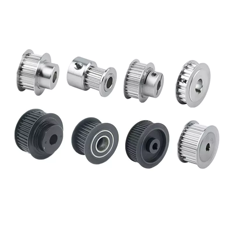
How to Assemble a Pulley System

A pulley is a wheel that rotates on a shaft or shaft to support the movement of a taut cable. Pulleys allow power to be transmitted from the shaft to the cable.
pulley

Simple pulley

The simplest theory of operation of a pulley system assumes that the rope and weight are weightless and that the rope and pulley are not stretched. Since the force on the pulley is the same, the force on the pulley shaft must also be zero. Therefore, the force exerted on the pulley shaft is also distributed evenly between the 2 wires passing through the pulley. The force distribution is shown in Figure 1.
The use of simple pulleys is as old as history. Before the Industrial Revolution, people relied on muscle strength to carry heavy loads. Pulleys, levers and ramps make this possible. Today, we can see pulleys in a variety of systems, from exercise equipment to garage doors, and even rock climbers use them to help them reach greater heights. As you can see, these simple machines have been around for centuries and are used in everyday life.
Another simple pulley system is the pulley system. In this system, there is a fixed pulley at the top and a movable pulley at the bottom. The 2 pulleys are connected by a rope. This combination reduces the amount of work required to lift the load. Additionally, the ropes used in this system are usually made of rope and woven through the individual wheels of the pulley drum.
A pulley is an ingenious device that distributes weight evenly and can be used to lift heavy objects. It is easy to build and can be easily modified for a wide range of activities. Even young children can make their own with very few materials. You can also use simple household items such as washing machines, thin textbooks and even chopsticks. It’s very useful and can be a great addition to your child’s science and engineering activities.
The simplest pulley system is movable. The axis of the movable pulley can move freely in space. The load is attached to 1 end of the pulley and the other end to the stationary object. By applying force on the other end of the rope, the load is lifted. The force at the other end of the rope is equal to the force at the free end of the pulley.
Another form of pulley is the compound pulley. Compound pulleys use 2 or more wheels to transmit force. Compound pulleys have 2 or more wheels and can lift heavier objects. Dim is POLE2.
pulley

tapered pulley

It is important to clean and align the bolt holes before assembling the tapered pulley. The screws should be lubricated and the threads cleaned before installation. To install the pulley, insert it into the shaft keyway. The keyway should be aligned with the shaft hole to prevent foreign matter from entering the pulley. Then, alternately tighten the bolts until the pulley is tightened to the desired torque.
A tapered pulley is a basic structure. The pulley belt is arranged across 4 steps. Installed between the headstock casting and the main shaft, it is often used in the paper industry. It integrates with printing machinery and supports assembly lines. These pulleys are also available in metric range options, eliminating the need for ke-waying or re-drilling. They are easy to install, and users can even customize them to suit their needs.
CZPT Private Limited is a company that provides unique products for various industries. This large product is used for many different purposes. Also, it is manufactured for industrial use. The company’s website provides detailed specifications for the product. If you need a tapered pulley, contact a company in your area today to purchase a quality product!
Tapered pulleys are vital to paper mill machinery. Its special design and construction enable it to transmit power from the engine source to the drive components. The advantages of this pulley include low maintenance costs and high mechanical strength. Cone wheel diameters range from 10 inches to 74 inches. These pulleys are commonly used in paper mills as they offer low maintenance, high mechanical strength and low wear.
A tapered sleeve connects the pulley to the shaft and forms an interference fit connector. The taper sleeve is fixed on the shaft with a key, and the corresponding inner hole is fixed on the shaft with a key. These features transmit torque and force to the pulley through friction. This allows the tapered pulley to move in a circular motion. The torque transfer characteristics of this pulley are most effective in high speed applications.
The sleeve is the most important part when assembling the tapered pulley. There is an 8-degree taper inside the cone, which is closely connected to the inner surface of the pulley. Taper sleeves and pulleys are interchangeable. However, tapered pulleys can be damaged after prolonged use.
pulley

pulley pulley system

A pulley pulley system is a great way to move heavy objects. These systems have been around for centuries, dating back to the ancient Greeks. This simple mechanism enables a person to lift heavy objects. These blocks are usually made of rope, and the number of turns varies for different types of rope. Some blocks have more cords than others, which creates friction and interferes with the easy movement of the lifting system.
When using a pulley pulley, the first thing to decide is which direction to pull. Unfavorable rigging means pulling in the opposite direction. In theory, this method is less efficient, but sometimes requires a certain amount of work space. The benefit is that you will increase the mechanical advantage of the pulley by pulling in the opposite direction. So the interception and tackle system will give you more of a mechanical advantage.
Pulley pulleys are an excellent choice for lifting heavy objects. The system is simple to install and users can easily lift objects without extensive training. Figure 3.40 shows a pulley in action. In this photo, the person on the left is pulling a rope and tying the end of the rope to a weight. When the rope is attached to the load, the rope will be pulled over the pulley and pulley.
The blocks on the blocks are attached to the ends of the rope. This creates unique lifting advantages compared to single-line systems. In Figure 3, the tension of each thread is equal to one-third of the unit weight. When the rope is pulled over the pulley, the force is divided equally between the 2 wires. The other pulley reverses the direction of the force, but that doesn’t add any advantage.
Use pulleys to reduce traction and load. The weight of the load has not changed, but the length of the rope has increased. Using this method, lifting the load by pulling the rope 4 times reduces the force required to lift 1 foot. Likewise, if the pulley system had 4 pulleys instead of three, the length of the rope would be tripled.
The system can transmit loads in any direction. Rope length is determined by multiplying the distance from the fixed block to the load by the mechanical advantage. If the mechanical advantage is 3:1, then passing the rope through the pulley 3 times will produce the required traction distance. Also, the length of the rope will depend on the mechanical advantage, so if the load is 3 times the length of the rope, it will be more than 3 times the required length.

China Standard Agro Farm Implements 3 Point Hitch Tractor Pto Finish Mower Grass Cutter FM 180     near me manufacturer China Standard Agro Farm Implements 3 Point Hitch Tractor Pto Finish Mower Grass Cutter FM 180     near me manufacturer

China supplier Agriculture Farm Mower Tractor Linkage Grass Toppers Weed Cutter near me factory

Product Description

Product Description
Specification:
1.3 point linkage
2. Graphite casting iron gearbox
3. Tractor power required: 18-30HP
4. With CE certificate

TM90-140: 48-21 sets in 20ft container, 96-43sets in 40ft container and 112-50 sets in 40HQ.
Production time: 22 -30 working days.

Description
Function
1. It is used for cutting higher weeds in the field, and also suitable for bushes or rougher weeds.
2. It cuts grass by high-speed operation and dead weight of blades.

Performance
1. Gearbox is made of graphite casting iron, with better material performance, not easy broken.
2. With adjustable rear wheel (option), it can prevent the body tail sinking, and the spacers above it can adjust the cutting height.
3. Blade spacers between up and down blade seat plates or connection plates can be replaced more easily after wearing, and the replacement cost will be smaller.
4. The improved model has more and denser blades to improve cutting efficiency, and the blades are thicker and heavier, not easy to break when meeting hard objects.
5. The machine is more durable and works more stably due to its heavier weight.
6. The blades are thicker, and the plates around has been strengthened. Two blades and 3 blades can be chosen according to different needs.
7. With front protection chain, it can prevent splashing.
8. Cat. I universal three-point hitch cardan shaft.

Company Introduction

HangZhou CZPT Industry & Trade Co., Ltd., is a professional manufacturer and exporter of whole set of farm machines and garden tools for 11 years, mainly including mowers, tillers, plows and Japanese tractor parts, etc.
We sincerely welcome customers abroad to visit us to discuss cooperation and seek common development. We believe our company is your most reliable partner and friend!

Machine Improvement
1. The old design was square with 2 blades, but now new design is disc with 3 blades. It has denser blades and can improve the cutting efficiency.
2. There were 5 holes on the wear plate before, but now there are 3 holes on the wear plate. It will be more convenient to replace them after improvement.

Company Overview
LEFA always invites foreign customers to visit company and test machinery. And it pays attention to the development of staff and provides abundant training for staff to improve ourselves.
Besides, CZPT insists on organizing staff to tour once a year and encourage staff to join more activities, to let us have an appointment with nature, enjoying the pleasure of life in our busy spare time.

FAQ
1. Trade terms: FOB, CIF, EXW
2. Sample Policy: You can test the quality of our sample firstly before you purchase them in mass quantity.
3. MOQ: 1 set
4. Payment Way: T/T, L/C, Western Union, D/P.
5. Delivery Date: 10-30 days after deposit paid. It depends on your order quantity.
6. Shipping Way: By Sea or By Air.
7. After Service: 12 months guarantee of the main parts, we will send the guarantee parts together with the machine in your next order or we can send them by air express if you need them urgently.


How to Identify a Faulty Drive Shaft

The most common problems associated with automotive driveshafts include clicking and rubbing noises. While driving, the noise from the driver’s seat is often noticeable. An experienced auto mechanic can easily identify whether the sound is coming from both sides or from 1 side. If you notice any of these signs, it’s time to send your car in for a proper diagnosis. Here’s a guide to determining if your car’s driveshaft is faulty:
air-compressor

Symptoms of Driveshaft Failure

If you’re having trouble turning your car, it’s time to check your vehicle’s driveshaft. A bad driveshaft can limit the overall control of your car, and you should fix it as soon as possible to avoid further problems. Other symptoms of a propshaft failure include strange noises from under the vehicle and difficulty shifting gears. Squeaking from under the vehicle is another sign of a faulty driveshaft.
If your driveshaft fails, your car will stop. Although the engine will still run, the wheels will not turn. You may hear strange noises from under the vehicle, but this is a rare symptom of a propshaft failure. However, you will have plenty of time to fix the problem. If you don’t hear any noise, the problem is not affecting your vehicle’s ability to move.
The most obvious signs of a driveshaft failure are dull sounds, squeaks or vibrations. If the drive shaft is unbalanced, it is likely to damage the transmission. It will require a trailer to remove it from your vehicle. Apart from that, it can also affect your car’s performance and require repairs. So if you hear these signs in your car, be sure to have it checked by a mechanic right away.

Drive shaft assembly

When designing a propshaft, the design should be based on the torque required to drive the vehicle. When this torque is too high, it can cause irreversible failure of the drive shaft. Therefore, a good drive shaft design should have a long service life. Here are some tips to help you design a good driveshaft. Some of the main components of the driveshaft are listed below.
Snap Ring: The snap ring is a removable part that secures the bearing cup assembly in the yoke cross hole. It also has a groove for locating the snap ring. Spline: A spline is a patented tubular machined element with a series of ridges that fit into the grooves of the mating piece. The bearing cup assembly consists of a shaft and end fittings.
U-joint: U-joint is required due to the angular displacement between the T-shaped housing and the pinion. This angle is especially large in raised 4x4s. The design of the U-joint must guarantee a constant rotational speed. Proper driveshaft design must account for the difference in angular velocity between the shafts. The T-bracket and output shaft are attached to the bearing caps at both ends.
air-compressor

U-joint

Your vehicle has a set of U-joints on the driveshaft. If your vehicle needs to be replaced, you can do it yourself. You will need a hammer, ratchet and socket. In order to remove the U-joint, you must first remove the bearing cup. In some cases you will need to use a hammer to remove the bearing cup, you should be careful as you don’t want to damage the drive shaft. If you cannot remove the bearing cup, you can also use a vise to press it out.
There are 2 types of U-joints. One is held by a yoke and the other is held by a c-clamp. A full ring is safer and ideal for vehicles that are often used off-road. In some cases, a full circle can be used to repair a c-clamp u-joint.
In addition to excessive torque, extreme loads and improper lubrication are common causes of U-joint failure. The U-joint on the driveshaft can also be damaged if the engine is modified. If you are driving a vehicle with a heavily modified engine, it is not enough to replace the OE U-joint. In this case, it is important to take the time to properly lubricate these components as needed to keep them functional.

tube yoke

QU40866 Tube Yoke is a common replacement for damaged or damaged driveshaft tubes. They are desirably made of a metallic material, such as an aluminum alloy, and include a hollow portion with a lug structure at 1 end. Tube yokes can be manufactured using a variety of methods, including casting and forging. A common method involves drawing solid elements and machining them into the final shape. The resulting components are less expensive to produce, especially when compared to other forms.
The tube fork has a connection point to the driveshaft tube. The lug structure provides attachment points for the gimbal. Typically, the driveshaft tube is 5 inches in diameter and the lug structure is 4 inches in diameter. The lug structure also serves as a mounting point for the drive shaft. Once installed, Tube Yoke is easy to maintain. There are 2 types of lug structures: 1 is forged tube yoke and the other is welded.
Heavy-duty series drive shafts use bearing plates to secure the yoke to the U-joint. All other dimensions are secured with external snap rings. Yokes are usually machined to accept U-bolts. For some applications, grease fittings are used. This attachment is more suitable for off-road vehicles and performance vehicles.
air-compressor

end yoke

The end yoke of the drive shaft is an integral part of the drive train. Choosing a high-quality end yoke will help ensure long-term operation and prevent premature failure. Pat’s Driveline offers a complete line of automotive end yokes for power take-offs, differentials and auxiliary equipment. They can also measure your existing parts and provide you with high quality replacements.
A U-bolt is an industrial fastener with threaded legs. When used on a driveshaft, it provides greater stability in unstable terrain. You can purchase a U-bolt kit to secure the pinion carrier to the drive shaft. U-bolts also come with lock washers and nuts. Performance cars and off-road vehicles often use this type of attachment. But before you install it, you have to make sure the yoke is machined to accept it.
End yokes can be made of aluminum or steel and are designed to provide strength. It also offers special bolt styles for various applications. CZPT’s drivetrain is also stocked with a full line of automotive flange yokes. The company also produces custom flanged yokes for many popular brands. Since the company has a comprehensive line of replacement flange yokes, it can help you transform your drivetrain from non-serviceable to serviceable.

bushing

The first step in repairing or replacing an automotive driveshaft is to replace worn or damaged bushings. These bushings are located inside the drive shaft to provide a smooth, safe ride. The shaft rotates in a rubber sleeve. If a bushing needs to be replaced, you should first check the manual for recommendations. Some of these components may also need to be replaced, such as the clutch or swingarm.

China supplier Agriculture Farm Mower Tractor Linkage Grass Toppers Weed Cutter     near me factory China supplier Agriculture Farm Mower Tractor Linkage Grass Toppers Weed Cutter     near me factory

China wholesaler Farm Machinery Tractor Mounted 3-Point Finishing Mower with Ce with Good quality

Product Description

Specification:  

  1. 3 point linkage
  2. Graphite casting iron gearbox
  3. Tractor power required: 18-35hp

Product Attribute

  1. Transmission: V belt transmission, more reliable.
  2. Graphite gearbox is made of casting iron.  Material performance is better. Not easy broken.
  3. 3 parallel blades are working meanwhile, expanding the cutting width.
  4. Blade shaft seat is made of casting iron. More reliable and strong.  
  5. Rear-discharge and side-discharge can be selectable for you.
  6. The wheel is clad in rubber, more stable and wear-resistant.
  7. Mainly for cutting grass in the flat area.
  8. Mowing height can be adjusted.

Product Display

Specifications

Model FM-100 FM-120 FM-150 FM-180
Dimension(mm) 1100x1100x700 1260x1200x650 1570x1200x650 1860x1350x650
Weight(kg) 150 185 200 225
Cutting Width 100cm 120cm 150cm 180cm
PTO input Speed 540r/min 540r/min 540r/min 540r/min
Power Required 16-25hp 18-25hp 20-30hp 20-35hp
Packing size(mm) 1200x1150x2200 1400x760x2200 1700x860x2200 2000x1100x2200

Product Detail

Company Profile                                                             

HangZhou CZPT Industry & Trade Co., Ltd., is a professional manufacturer and exporter of whole set of agriculture machines and garden tools. Our company was established since 2003 with Hanma Industry Company.

Our main products include rotovator, flail mower, finishing mower, CZPT mower, wood chipper, plow, cultivator, potato harvester/ planter and Japanese tractor parts, etc. Due to our super International quality standard and rapid & excellent after-sales service, CZPT machines are greatly popular in various markets around the world, and already reached to Europe, North America, South America, Australia, almost covers 80 countries in World.

LEFA always believe that we will take better farming life to you by top-quality laser cutting machine & CNC bending machine & professional paint-spraying & strong welding.


Packing & Shipping                                                                      

Packaging Detail: Iron pallet or wooden cases
Delivery Detail: By sea or By air
1. Waterproof packing with the international export standard by 20ft, 40ftcontainer.
Wooden Case or Iron Pallet.
2. The whole set of machines size are large as normal, so we will use Waterproof materials to pack
all of them. The motor, gear box or other easily damaged parts, we will put them into box. 

Machine videos in YOUTOBE                                       
          EFDL SIDE MOWERS

         EFG FLAIL MOWERS   

         EFGL SIDE MOWERS

          FM FINISHING MOWERS

        TM CZPT MOWERS

            RT ROTARY TILLERS

  Wood chipper BRH80 
https://youtu.be/66geQQOUTLY                        wood chipper BX-42

FAQ:                                                                               
Q1. How to buy finish mower?
Inquiry ———> Quotation ——–>Price reasonable ——->Check with specification —–>Proforma Invoice sent ————>Payment made ——-> Producing the items ——->Product shipment ———–> Customer confirm

Q2.How long is the delivery date for finish mower?
A:In general, we can ship the goods within 30-45 days after receiving your payment. Of course, it also depends on your quantity.

Q3. How can I get to your factory to buy finish mower?
A:We are located in HangZhou, only 1 hour’s distance to ZheJiang or HangZhou. You can fly to ZheJiang /HangZhou/HangZhou Airport , the transportation is very convenient

Q4.Do you have stock for finish mower?
A:In general, we have some stock, while if you need a bulk order, we still need time to produce it. Of course, we will inform all details you before your payment.

Q5: What’s your main products?
A: Our products are covered almost all farm machines and Japanese tractors parts, we can meet your any demands.

Q6. What is your terms of payment?
A: T/T, L/C, Paypal, Western Union
 

Axle Spindle Types and Features

The axle spindle is an integral part of your vehicle’s suspension. There are several different types and features, including mounting methods, bearings, and functions. Read on for some basic information on axle spindles. The next part of the article will cover how to choose the correct axle spindle for your vehicle. This article will also discuss the different types of spindles available, including the differences between the rear and front bearings.
Driveshaft

Features

The improved axle spindle nut assembly is capable of providing additional performance benefits, including increased tire life and reduced seal failure. Its keyway features and radially inwardly extending teeth allow nut adjustment to be accomplished with precision. The invention further provides a unique, multi-piece locking mechanism that minimizes leakage and torque transfer. Its principles and features are detailed in the appended claims. For example, the improved axle spindle nut assembly is designed for use in vehicles that are equipped with a steering system.
The axle spindle nut assembly includes a nut 252 with threads 256 on its inner periphery. The axle spindle 50 also features threads 198 on its outer periphery. The nut is threaded onto the outboard end of the axle spindle 50 until it contacts the inboard surface of the axle spacer 26. In the assembled state, a bearing spacer 58 is also present on the axle spindle.
The axle spindle nut assembly can reduce axial end play between the wheel end assembly 52 and the axle spindle 50. It can be tightened to an extreme torque level, but if the thread faces separate, it will undercompress the bearing cone and spacer group. To minimize these disadvantages, the axle spindle nut assembly is a critical component of a wheel-end assembly. There are several types of axle spindle nuts.
The third embodiment of the axle spindle nut assembly 300 comprises an inner washer 202, an outer washer 310, and at least 1 screw 320. The axle spindle nut assembly 300 secures and preloads bearing cones 55, 57. Unlike the first embodiment, the axle spindle nut assembly 300 uses the inner washer 202, which is optional in the third embodiment. The inner washer 202 and outer washer 310 are similar to those of the first embodiment.

Functions

An axle spindle is 1 of the most important components of a vehicle’s suspension system. The spindle retains the position of bearings and a spacer in an axle by providing clamp force. The inner nut of an axle spindle should be properly torqued to ensure a secure fit. A spindle nut is also responsible for compressing bearings and spacers. If any of these components are missing, the spindle will not work properly.
An axle spindle is used in rear wheel drive cars. It carries the weight of the vehicle on the axle casing and transfers the torque from the differential to the wheels. The axle spindle and hub are secured on the spindle by large nuts. The axle spindle is a vital component of rear wheel drive vehicles. Hence, it is essential to understand the functions of axle spindle. These components are responsible for the smooth operation of a vehicle’s suspension system.
Axle spindles can be mounted in 3 ways: in the typical axle assembly, the spindles are bolted onto the ends of the tubular axle, and the axle is suspended by springs. Short stub-axle mounting uses a torsion beam that flexes to provide a smooth ride. A second washer is used to prevent excessive rotation of the axle spindle.
Apart from being a crucial component of the suspension system, the spindles of the wheels are responsible for guiding the vehicle in a straight line. They are connected to the steering axis and are used in different types of suspension systems. European cars use a MacPherson Strut suspension system in which the spindle is connected to the arms in the front and rear of the suspension frame. The MacPherson strut allows the shock absorber housing to turn the wheel.
Driveshaft

Methods of mounting

Various methods of mounting axle spindle are available. In general, these methods involve forming a tubular blank of uniform cross section and thickness, and receiving the bearing assembly against it. The spindle is then secured using a collar, which also serves as a bearing stop. In some cases, additional features are used to provide greater security. Some of these features may not be suitable for all applications. But they are generally suitable.
Axle spindle forming is usually done by progressive steps using hollow punches. The metallic body of the punch has an inner work surface, which receives the axle blank. A mandrel is fixed within the work opening of the punch. The punch body’s work surface forges the spindle about the mandrel. The punch has 2 ends, a closed and an open one.
A wheeled vehicle axle assembly (10) includes a cylindrical housing member (12 a) and a plurality of spindle mounting flanges (30) secured on the housing member. The spindles (16) are firmly attached to the housing member by means of coupling members. The coupling members are configured to distribute the bending loads imposed on the spindle by the axle. It is important to note that the coupling members can be either threaded or screwed.
Traditionally, axle spindles were made from tubular blanks of irregular thickness. This method allowed for a gradual reduction in diameter and eliminated the need for extra metal within the spindle. Similarly, axles made by cold forming eliminate the need for additional metal in the spindle. In this way, the overall cost of manufacture is also reduced. The material used for manufacturing axles also determines the size and shape of the final product.
Driveshaft

Bearings

A nut 16 is used to retain the wheel bearings on axle spindle 12. The nut comprises several parts. The first portion includes a plurality of threads and a deformable second portion. The nut may be disposed on the inboard or outboard end of the axle spindle. This type of nut is typically secured to the axle spindle by a retaining nut.
The bearings are installed in the spindle to allow the wheel hub to rotate. While bearings are greased, they can dry out over time. Consequently, you may hear a loud clicking sound when turning your vehicle. Alternatively, you may notice grease on the edges of your tires. Bearing failure can cause severe damage to your axle spindle. If you notice any of these symptoms, you may need to replace the bearings on your axle spindle. Fortunately, you can purchase the necessary bearing parts at O’Reilly Auto Parts.
There are 3 ways to mount an axle spindle. A typical axle assembly has the spindles bolted to the ends of the tubular axle. A torsion beam is also used to mount the spindles on the axle. This torsion beam acts like a spring to help make the ride smooth and bump-free. Lastly, the axle spindle is sometimes mounted as a bolt-on component.

Cost

If your axle spindle has been damaged, you may need to have it replaced. This part of the axle is relatively easy to replace, but you need to know how to do it correctly. To replace your axle spindle, you must first remove the damaged one. To do this, a technician will cut the weld. They will then thread the new 1 into the axle tube and torque it to specification. After that, they will weld the new axle spindle into place.
When you are thinking about the cost of an axle spindle replacement, you must first determine if it is worth it for your vehicle. It is generally a good idea to replace the spindle only if it is causing damage to your vehicle. You can also replace your axle housing if it is deteriorating. If you do not replace the spindle, you can risk damaging the axle housing. To save money, you can consider using a repair kit.
You can also purchase an axle nut socket set. Most wrenches have an adjusting socket for this purpose. The socket set should be suitable for most vehicle types. Axle spindle replacement costs around $500 to $600 before tax. However, you should be aware that these costs vary widely based on the type of vehicle you have. The parts can cost between $430 and $480, and the labor can cost anywhere from $50 to 70.

China wholesaler Farm Machinery Tractor Mounted 3-Point Finishing Mower with Ce     with Good qualityChina wholesaler Farm Machinery Tractor Mounted 3-Point Finishing Mower with Ce     with Good quality

China Hot selling Four-Wheel Drive 60HP Tractor/Mini Rice Harvester Tractor /Small Farm Grass Cutter with Best Quality near me factory

Product Description

This series of tractors can be matched with a variety of agricultural machinery and tools, and are generally suitable for small and medium-sized farm work and complex operations in pastures, and can meet a variety of operational needs. Equipped with a well-known brand engine, low noise, compact structure, light weight, low fuel consumption, the exterior is equipped with a streamlined hood, which has a more technological sense, isolates dust and protects the machinery. The seat is wide and comfortable, the vision is wide, the operation is convenient, the power is full, and the driving experience is comfortable.

 Product Parameter

Model / MK704
Type / 4*4
Use / General purpose
External dimensions (length*width*height) mm 3700*1550*2255
Wheelbase or track ground length mm 1990
Wheel base (front wheel/rear wheel) or gauge mm 1100,1200,1300,1400/1200,1300,1400,1500
Common track (front wheel/rear wheel) or gauge mm 1300/1400
Minimum ground clearance mm 420
Minimum use quality kg 2260
Standard counterweight (front/rear) kg 60/60
Maximum counterweight (front/rear) kg 60/180
Track ground pressure kpa /
PTO shaft power kw 44.8
main traction force KN 17
Number of cylinders / 4
Bore×stroke mm 93*102
Rated power kw 52
Rated speed   2400

This product can be used with a variety of agricultural machinery, such as rotary tillers, plows, seeders, harvesters, weeders, bulldozers, etc.It can be widely used in various fields, such as farmland, orchard, garden, greenhouse, and mountain. 

 Packing&Shipping
Factory inspection
After-sales service                                                                                                                              1.Free Technical Advisory Services
2.Give  suggestion for  fitful goods
3.Invite customer come
4.Let you know all satuation about  goods  produce ,packing 
5.Supply test  report and  sample test
6.Suppy support by vedio , Email , phone
7.Free easy  broken parts
8.Dispatch technicians for on-site teaching and maintenance
FAQ                                                                                                                                                     
Q1. Can the logo and color of the product be customized?
A1. Yes, it can be customized according to your needs, we welcome your sample customization.
Q2. What are the advantages of our company?
A2. Our company has a professional technical team and a professional production line to ensure the quality and delivery time of the product, provide good packaging to avoid damage during transportation, and deliver the goods to you in a timely and complete manner.
Q3. How to control the quality of products?
A3. We have always attached great importance to the control of product quality, consistently providing high-quality products, and implementing strict factory inspection procedures for each tractor to ensure the quality of each product.
Q4. How long can I receive the goods after placing the order?
A4. The delivery time is generally 1 month, and the specific time is adjusted according to the order quantity.
 

Screw Shaft Types

A screw shaft is a cylindrical part that turns. Depending on its size, it is able to drive many different types of devices. The following information outlines the different types of screws, including their sizes, material, function, and applications. To help you select the right screw shaft, consider the following factors:
screwshaft

Size

A screw can come in a variety of shapes and sizes, ranging from a quarter to a quarter-inch in diameter. A screw is a cylindrical shaft with an inclined plane wrapped around it, and its main function is to fasten objects together by translating torque into a linear force. This article will discuss the dimensions of screws and how to determine the size of a screw. It is important to note that screw sizes can be large and small depending on the purpose.
The diameter of a screw is the diameter of its shaft, and it must match the inner diameter of its nuts and washers. Screws of a certain diameter are also called machine screws, and they can be larger or smaller. Screw diameters are measured on the shaft underneath the screw head. The American Society of Mechanical Engineers (ASME) standardized screw diameters in 3/50-inch to 16 (3/8-inch) inches, and more recently, sizes were added in U.S. fractions of an inch. While shaft and head diameters are standardized, screw length may vary from job to job.
In the case of the 2.3-mm screw group, the construct strength was not improved by the 1.2-mm group. The smaller screw size did not increase the strength of the construct. Further, ABS material did not improve the construct strength. Thus, the size of screw shaft is an important consideration in model design. And remember that the more complex your model is, the larger it will be. A screw of a given size will have a similar failure rate as a screw of a different diameter.
Although different screw sizes are widely used, the differences in screw size were not statistically significant. Although there are some limitations, screws of different sizes are generally sufficient for fixation of a metacarpal shaft fracture. However, further clinical studies are needed to compare screw sizes for fracture union rates. So, if you are unsure of what size of screw shaft you need for your case, make sure to check the metric chart and ensure you use the right one.
screwshaft

Material

The material of a screw shaft plays an important role in the overall performance of a screw. Axial and central forces act to apply torque to the screw, while external forces, such as friction, exert a bending moment. The torsional moments are reflected in the torque, and this causes the screw to rotate at a higher rate than necessary. To ensure the longevity of the screw, the material of the screw shaft should be able to handle the bending moment, while the diameter of the shaft should be small enough to avoid causing damage.
Screws are made from different metals, such as steel, brass, titanium, and bronze. Manufacturers often apply a top coating of chromium, brass, or zinc to improve corrosion resistance. Screws made of aluminum are not durable and are prone to rusting due to exposure to weather conditions. The majority of screw shafts are self-locking. They are suited for many applications, including threaded fasteners, C-clamps, and vises.
Screws that are fabricated with conical sections typically feature reduced open cross-sectional areas at the discharge point. This is a key design parameter of conical screw shafts. In fact, reductions of up to 72% are common across a variety of applications. If the screw is designed to have a hard-iron hanger bearing, it must be hardened. If the screw shaft is not hardened, it will require an additional lubricant.
Another consideration is the threads. Screw shafts are typically made of high-precision threads and ridges. These are manufactured on lathes and CNC machines. Different shapes require different materials. Materials for the screw shaft vary. There are many different sizes and shapes available, and each 1 has its own application. In addition to helical and conical screw shafts, different materials are also available. When choosing material, the best 1 depends on the application.
The life of the screw depends on its size, load, and design. In general, the material of the screw shaft, nut body, and balls and rollers determine its fatigue life. This affects the overall life of the screw. To determine whether a specific screw has a longer or shorter life, the manufacturer must consider these factors, as well as the application requirements. The material should be clean and free of imperfections. It should be smooth and free of cracks or flaking, which may result in premature failure.

Function

The function of a screw shaft is to facilitate the rotation of a screw. Screws have several thread forms, including single-start, double-start and multi-start. Each form has its own advantages and disadvantages. In this article we’ll explore each of them in detail. The function of a screw shaft can vary based on its design, but the following are common types. Here are some examples of screw shaft types and their purposes.
The screw’s torque enables it to lift objects. It can be used in conjunction with a bolt and nut to lift a load. Screws are also used to secure objects together. You can use them in screw presses, vises, and screw jacks. But their primary function is to hold objects together. Listed below are some of their main functions. When used to lift heavy loads, they can provide the required force to secure an object.
Screws can be classified into 2 types: square and round. Square threads are more efficient than round ones because they apply 0deg of angle to the nut. Square threads are also stronger than round threads and are often used in high-load applications. They’re generally cheaper to manufacture and are more difficult to break. And unlike square threads, which have a 0deg thread angle, these threads can’t be broken easily with a screwdriver.
A screw’s head is made of a series of spiral-like structures that extend from a cylindrical part to a tip. This portion of the screw is called the shank and is made of the smallest area. The shank is the portion that applies more force to the object. As the shaft extends from the head, it becomes thinner and narrow, forming a pointed tip. The head is the most important part of the screw, so it needs to be strong to perform its function.
The diameter of the screw shaft is measured in millimeters. The M8 screw has a thread pitch of 1.25 mm. Generally, the size of the screw shaft is indicated by the major and minor diameter. These dimensions are appended with a multiplication sign (M8x1).
screwshaft

Applications

The design of screws, including their size and shape, determines their critical rotating speeds. These speeds depend on the threaded part of the screw, the helix angle, and the geometry of the contact surfaces. When applied to a screw, these limits are referred to as “permissible speed limits.” These maximum speeds are meant for short periods of time and optimized running conditions. Continuous operation at these speeds can reduce the calculated life of a nut mechanism.
The main materials used to manufacture screws and screw shafts include steel, stainless steel, titanium, bronze, and brass. Screws may be coated for corrosion resistance, or they may be made of aluminium. Some materials can be threaded, including Teflon and nylon. Screw threads can even be molded into glass or porcelain. For the most part, steel and stainless steel are the most common materials for screw shafts. Depending on the purpose, a screw will be made of a material that is suitable for the application.
In addition to being used in fasteners, screw shafts are used in micrometers, drillers, conveyor belts, and helicopter blades. There are numerous applications of screw shafts, from weighing scales to measuring lengths. If you’re in the market for a screw, make sure to check out these applications. You’ll be happy you did! They can help you get the job done faster. So, don’t delay your next project.
If you’re interested in learning about screw sizing, then it’s important to know the axial and moment loads that your screws will experience. By following the laws of mechanics and knowing the load you can calculate the nominal life of your screw. You can also consider the effect of misalignment, uneven loading, and shocks on your screw. These will all affect the life of your screw. Then, you can select the right screw.

China Hot selling Four-Wheel Drive 60HP Tractor/Mini Rice Harvester Tractor /Small Farm Grass Cutter with Best Quality     near me factory China Hot selling Four-Wheel Drive 60HP Tractor/Mini Rice Harvester Tractor /Small Farm Grass Cutter with Best Quality     near me factory

China OEM Four-Wheel Drive 90HP Farm Tractor/Mini Rice Harvester Tractor /Small Garden Grass Cutter with Cab for Agriculture with Free Design Custom

Product Description

The power range of this series of tractors covers 50-120hp and can be matched with various implements. It is generally suitable for small and medium farmland and complex operations in pastures, and can meet a variety of operational needs. Equipped with an advanced four-post luxury cab, with smooth lines and a sense of technology, the seat is wide and comfortable, with a wide field of vision, equipped with multi-function effects, more flexible operation, and air conditioning, fans, and a comfortable driving experience.
Product Parameter

Power(hp) / 90HP
Type / Wheel type
Driving type / 4WD
External dimension (L × W × H) mm 4000×1850×2700(Cabin top)
Commonly used wheel tread(front/rear) or gauge mm 1250/1400
wheel tread(front/rear) or gauge mm 1250,1305,1405/1250-1560
Minimum ground clearance and position mm 370 (bottom of traction plate)
Minimum weight kg 2750
Standard Counterweight (Front/Rear) kg 130/75
Number of gears (forward/backward) / 12/12
Maximum theoretical design speed km/h 33.59
Engine intake mode / turbocharging
Number of engine cylinders / 4
Engine nominal power kW 66.15
Engine calibration speed r/min 2400
Hydraulic suspension system type / separate
Type of suspension / Three-point rear suspension
Standard speed of power output shaft r/min 540/720

With agricultural machinery
Can be applied to

Packing&ShippingFactory inspection
HangZhou Guihua Agricultural Equipment Co., Ltd. is located in HangZhou City, ZheJiang Province. It is a private enterprise group specializing in the design, production and sales of agricultural machinery. Its main products include tractors ranging from 25 hp to 260 hp, and micro farm tools ranging from 12 hp to 25 hp. The products are sold to more than 20 countries. The company’s products enter the domestic and foreign markets with high-tech content, well-known memory, performance docking, and value-added services. High-quality products and satisfactory service. All employees of our company wholeheartedly welcome customers to come to cooperate.
After-sales service
Free Technical Advisory Services
Give  suggestion for  fitful goods
Invite customer come
Let you know all satuation about  goods  produce ,packing 
Supply test  report and  sample test
Suppy support by vedio , Email , phone
Free easy  broken parts
Dispatch technicians for on-site teaching and maintenance
We are at your service 24 hours a day.
FAQ
Q1. Can the logo and color of the product be customized?
A1. Yes, it can be customized according to your needs, we welcome your sample customization.
Q2. What are the advantages of our company?
A2. Our company has a professional technical team and a professional production line to ensure the quality and delivery time of the product, provide good packaging to avoid damage during transportation, and deliver the goods to you in a timely and complete manner.
Q3. How to control the quality of products?
A3. We have always attached great importance to the control of product quality, consistently providing high-quality products, and implementing strict factory inspection procedures for each tractor to ensure the quality of each product.
Q4. How long can I receive the goods after placing the order?
A4. The delivery time is generally 1 month, and the specific time is adjusted according to the order quantity.

Advantages of Ball Bearings

What is a ball bearing? A ball bearing is a type of rolling-element bearing that utilizes balls to maintain separation between 2 bearing races. Its contact angle between the balls and the races helps it reduce friction between the loads. There are several advantages to ball bearings, including their ability to withstand water. Read on to learn more. Here are a few of the benefits. You can use them in your daily life, from your car to your boat.

Ball bearings reduce friction between loads

Ball bearings reduce friction between loads by constraining the relative motion between moving parts. These bearings consist of a ring of small metal balls that reduce friction between moving objects. The name “ball bearing” is derived from the verb “to bear.” The lubricant within the bearing reduces friction between moving particles. In a machine, ball bearings reduce friction between moving parts and improve linear motion around a fixed axis.
These bearings are commonly used to reduce friction between loads in rotating machines. They have 2 tracks, 1 fixed to the rotating part and 1 stationary. The rolling balls of a ball bearing have lower friction than flat surfaces. Because of this, they are useful for bar stool bearings. They reduce friction between surfaces and maintain the separation between bearing races. Hence, minimal surface contact is possible. Ball bearings have the potential to increase the life of machines and reduce energy consumption.
Ball bearings can be as small as a wrist watch or as large as an industrial motor. They function the same way, reducing friction between loads. Among their many uses, ball bearings are essential for everyday operations. Clocks, air conditioners, fans, and automobile axles all use ball bearings. In fact, anything that uses a motor requires ball bearings. It’s no wonder they’re gaining popularity in industries and everyday life.
bearing

They support radial and axial loads

Radial ball bearings are used primarily for radial loads, but they also have a capacity for axial load. This load capacity is usually given as a percentage of the radial load rating. Axial load capacity is generally greater for a bearing with a larger difference between the inner and outer ring diameters. The axial load capacity is also affected by the bearing’s raceway depth, with shallow raceways being more suitable for heavier axial loads.
The 2 main types of axial and radial loads are defined by their orientation. Axial loads apply forces in 1 direction while radial loads act on the opposite direction. In both cases, the bearing must support the forces that are imposed. Axial loads apply forces to a bearing in a single direction, while radial loads apply forces in both directions. Regardless of the type of load, axial and radial loads should be considered when selecting a bearing for a given application.
Angular and radial ball bearings differ in their materials. Radial ball bearings are made largely of through-hardened materials. They typically have a Rockwell hardness rating of 58 Rc. The raceways and balls of these bearings are made of 440C stainless steel. They may also contain shields and seals. SAE 52100 steel is the most common material for the raceway, while molybdenum steels are excellent for high temperatures.

They have a contact angle between the balls and the races

When comparing axial load bearings with their radial counterparts, the angular contact angle is more important. Axial load bearings, have a contact angle between the balls and the races of 35 degrees. They are suitable for axial loads and a limited radial load. The contact angle of these bearings is a result of the shape of the inner and outer rings. Each rolling element comes into contact with the inner and outer rings only at 1 point, forming a 30 degree angle with the radial plane. The radial force of the axial load on these bearings is therefore increased by increasing the contact angle between the balls and the races.
This contact angle determines the amount of friction between the balls and the races, and allows angular contact bearings to withstand heavy radial and thrust loads. In addition, the larger the contact angle, the greater the axial load support. Angular contact bearings come in standard imperial (inch) and metric (mm) sizes. The angular contact angle is determined by the free radial play value and the curvature of the inner track.

They are water-resistant

In addition to their water-resistant qualities, corrosion-resistant ball bearings can also protect against the damaging effects of corrosive environments. Generally, standard metals, such as steel, are susceptible to rust, which can significantly reduce their performance and extend the life of parts. However, plastics, stainless steel, and ceramics can provide corrosion-resistant ball bearings. And because these materials are much more durable, they offer other advantages, such as being easy to maintain.
Among the advantages of plastic ball bearings is their high resistance to extreme temperatures, high speeds, and corrosion. Depending on their construction, plastic bearings are often able to resist corrosion and anti-static properties. They’re lightweight and inexpensive compared to steel ball bearings. CZPT Sales Corporation was established in 1987 with a modest turnover of 4 lacs. As of the last financial year, it has grown to 500 lacs in sales.
Other advantages of water-resistant ball bearings include corrosion resistance, which is a key consideration in many applications. While stainless steel is highly corrosion-resistant, it decreases the bearing’s load-carrying capacity. Also, corrosion-resistant deep groove ball bearings are usually made with a specified internal clearance, which absorbs loss in clearance during mounting and shaft expansion. This factor affects their performance, and if these are compromised, a replacement may be necessary.
bearing

They are tough

A few things make ball bearings tough: they’re made of real materials, which means that they have inherent imperfections. Grade-1 balls are made especially for high-stress applications, such as Formula One engines. Grade-3 balls, on the other hand, strike the perfect balance between performance and cost. Ceramic balls, for example, are made to spin at a high rate of 400 RPM, and they’re finished with a mirror finish.
A steel carbon ball bearing is 1 of the toughest forms of ball bearings available. The material is incredibly strong, but the contact between the balls isn’t the best. Low-carbon steel is best for linear shafting and is usually coated with a polymer to prevent damage. Steel ball bearings with moderate amounts of carbon are tough, durable, and water-resistant. They’re ideal for gears, but their high-carbon steel counterparts are particularly tough and can resist corrosion.
A ceramic ball bearing is another option. This type has steel inner and outer rings but ceramic balls. Ceramic balls can withstand higher temperatures than steel and are also electrically insulating. Ceramic ball bearings also tend to be lighter and are more resistant to wear and tear. They’re also ideal for applications in which grease is not an option, such as in space shuttles. Despite the fact that ceramic ball bearings are tough, they’re still cheaper than steel ball bearings.

They are conductive

You may have heard the term “ball bearing” if you’ve studied introductory physics. What does that mean? Essentially, ball bearings are conductive because of their ability to conduct electricity. This ability is reflected in the charge distribution on the surface of the ball. Positive charges are drawn toward the positive plate, while negative charges are drawn away from the positively charged ball bearing. You may have even seen a ball bearing in action.
However, despite their conductive nature, ball bearings can still become damaged by electrical discharge. A higher voltage can cause the balls to pit, and the raceways to become uneven. These uneven surfaces will first show up as excessive noise, and eventually cause the bearing to malfunction. Fortunately, engineers have found a way to counter this problem: conductive grease. This grease enables current to flow through the ball bearing, preventing both heat and voltage buildup.
The difference between steel and ceramic ball bearings is their density. Steel bearings are more conductive than glass or hybrid ceramics. Steel ball bearings have an even grain structure and are conductive for resonance flow. When moving fast, the air surrounding the steel ball bearing carries resonance from the inner ring to the outer. This makes them ideal for high-speed resonance transfer. In addition to being conductive, glass microbeads are harder and lighter than steel.
bearing

They are used in pulley systems

Pulley systems use ball bearings to move the sprocket, which is a wheel that rotates. These bearings are installed on the center mounting hole of the pulley wheel. They protect the entire system from heat, while allowing higher speed and smooth operation. They distribute the weight of the load evenly, minimizing friction and wobbling, and ensure a smooth rotation. Ball bearings are typically made from steel and are installed inside the pulley wheel.
The moment of inertia and bearing friction are measured to within 10 percent accuracy. These 2 variables affect the speed of the pulley system, which can lead to crashes if the weight holders are not balanced. Therefore, ball bearings are used to minimize the chance of such crashes. When you want to know more about ball bearings in pulley systems, here are the advantages they provide.
Another benefit of ball bearings in pulley systems is that they have lower friction than their solid counterparts. In order to reduce friction, however, ball bearings must be made of good materials. Some of the common ball materials are high-quality plastics and stainless steel. Good materials and clever block design are essential to minimizing friction. If you are planning to use ball bearings in your pulley system, check out the following tips and make sure you are choosing the right 1 for your application.
China OEM Four-Wheel Drive 90HP Farm Tractor/Mini Rice Harvester Tractor /Small Garden Grass Cutter with Cab for Agriculture     with Free Design CustomChina OEM Four-Wheel Drive 90HP Farm Tractor/Mini Rice Harvester Tractor /Small Garden Grass Cutter with Cab for Agriculture     with Free Design Custom