Condition: Utilized
Warranty: 3 years
Applicable Industries: Creating Material Shops, Manufacturing Plant, Farms, Design works , Other
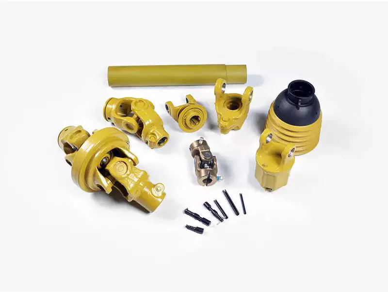
Excess weight (KG): twenty five Exhaust Filter For CZPT RA5710 Vacuum Pump Oil Mist Separator Filter Factor 1200,1300 adjustable

What Is a Gearbox?
There are several factors to consider when choosing a gearbox. Backlash, for example, is a consideration, as it is the angle at which the output shaft can rotate without the input shaft moving. While this isn’t necessary in applications without load reversals, it is important for precision applications involving load reversals. Examples of these applications include automation and robotics. If backlash is a concern, you may want to look at other factors, such as the number of teeth in each gear.
Function of a gearbox
A gearbox is a mechanical unit that consists of a chain or set of gears. The gears are mounted on a shaft and are supported by rolling element bearings. These devices alter the speed or torque of the machine they are used in. Gearboxes can be used for a wide variety of applications. Here are some examples of how gearboxes function. Read on to discover more about the gears that make up a gearbox.
Regardless of the type of transmission, most gearboxes are equipped with a secondary gear and a primary one. While the gear ratios are the same for both the primary and secondary transmission, the gearboxes may differ in size and efficiency. High-performance racing cars typically employ a gearbox with two green and one blue gear. Gearboxes are often mounted in the front or rear of the engine.
The primary function of a gearbox is to transfer torque from one shaft to another. The ratio of the driving gear’s teeth to the receiving member determines how much torque is transmitted. A large gear ratio will cause the main shaft to revolve at a slower speed and have a high torque compared to its counter shaft. Conversely, a low gear ratio will allow the vehicle to turn at a lower speed and produce a lower torque.
A conventional gearbox has input and output gears. The countershaft is connected to a universal shaft. The input and output gears are arranged to match the speed and torque of each other. The gear ratio determines how fast a car can go and how much torque it can generate. Most conventional transmissions use four gear ratios, with one reverse gear. Some have two shafts and three inputs. However, if the gear ratios are high, the engine will experience a loss of torque.
In the study of gearbox performance, a large amount of data has been collected. A highly ambitious segmentation process has yielded nearly 20,000 feature vectors. These results are the most detailed and comprehensive of all the available data. This research has a dual curse – the first is the large volume of data collected for the purpose of characterization, while the second is the high dimensionality. The latter is a complication that arises when the experimental gearbox is not designed to perform well.
Bzvacklash
The main function of a gearhead is to multiply a moment of force and create a mechanical advantage. However, backlash can cause a variety of issues for the system, including impaired positioning accuracy and lowered overall performance. A zero backlash gearbox can eliminate motion losses caused by backlash and improve overall system performance. Here are some common problems associated with backlash in gearheads and how to fix them. After you understand how to fix gearbox backlash, you’ll be able to design a machine that meets your requirements.
To reduce gearbox backlash, many designers try to decrease the center distance of the gears. This eliminates space for lubrication and promotes excessive tooth mesh, which leads to premature mesh failure. To minimize gearbox backlash, a gear manufacturer may separate the two parts of the gear and adjust the mesh center distance between them. To do this, rotate one gear with respect to the fixed gear, while adjusting the other gear’s effective tooth thickness.
Several manufacturing processes may introduce errors, and reducing tooth thickness will minimize this error. Gears with bevel teeth are a prime example of this. This type of gear features a small number of teeth in comparison to its mating gear. In addition to reducing tooth thickness, bevel gears also reduce backlash. While bevel gears have fewer teeth than their mating gear, all of their backlash allowance is applied to the larger gear.
A gear’s backlash can affect the efficiency of a gearbox. In an ideal gear, the backlash is zero. But if there is too much, backlash can cause damage to the gears and cause it to malfunction. Therefore, the goal of gearbox backlash is to minimize this problem. However, this may require the use of a micrometer. To determine how much gearbox backlash you need, you can use a dial gauge or feeler gauge.
If you’ve been looking for a way to reduce backlash, a gearbox’s backlash may be the answer. However, backlash is not a revolt against the manufacturer. It is an error in motion that occurs naturally in gear systems that change direction. If it is left unaccounted for, it can lead to major gear degradation and even compromise the entire system. In this article, we’ll explain how backlash affects gears and how it affects the performance of a gearbox.
Design
The design of gearboxes consists of a variety of factors, including the type of material used, power requirements, speed and reduction ratio, and the application for which the unit is intended. The process of designing a gearbox usually begins with a description of the machine or gearbox and its intended use. Other key parameters to consider during gearbox design include the size and weight of the gear, its overall gear ratio and number of reductions, as well as the lubrication methods used.
During the design process, the customer and supplier will participate in various design reviews. These include concept or initial design review, manufacturing design validation, critical design review, and final design review. The customer may also initiate the process by initiating a DFMEA. After receiving the initial design approval, the design will go through several iterations before the finalized design is frozen. In some cases, the customer will require a DFMEA of the gearbox.
The speed increaser gearboxes also require special design considerations. These gearboxes typically operate at high speeds, causing problems with gear dynamics. Furthermore, the high speeds of the unit increase frictional and drag forces. A proper design of this component should minimize the effect of these forces. To solve these problems, a gearbox should incorporate a brake system. In some cases, an external force may also increase frictional forces.
Various types of gear arrangements are used in gearboxes. The design of the teeth of the gears plays a significant role in defining the type of gear arrangement in the gearbox. Spur gear is an example of a gear arrangement, which has teeth that run parallel to the axis of rotation. These gears offer high gear ratios and are often used in multiple stages. So, it is possible to create a gearbox that meets the needs of your application.
The design of gearboxes is the most complex process in the engineering process. These complex devices are made of multiple types of gears and are mounted on shafts. They are supported by rolling element bearings and are used for a variety of applications. In general, a gearbox is used to reduce speed and torque and change direction. Gearboxes are commonly used in motor vehicles, but can also be found in pedal bicycles and fixed machines.
Manufacturers
There are several major segments in the gearbox market, including industrial, mining, and automotive. Gearbox manufacturers are required to understand the application and user industries to design a gearbox that meets their specific requirements. Basic knowledge of metallurgy is necessary. Multinational companies also provide gearbox solutions for the power generation industry, shipping industry, and automotive industries. To make their products more competitive, they need to focus on product innovation, geographical expansion, and customer retention.
The CZPT Group started as a small company in 1976. Since then, it has become a global reference in mechanical transmissions. Its production range includes gears, reduction gearboxes, and geared motors. The company was the first in Italy to achieve ISO certification, and it continues to grow into one of the world’s leading manufacturers of production gearboxes. As the industry evolves, CZPT focuses on research and development to create better products.
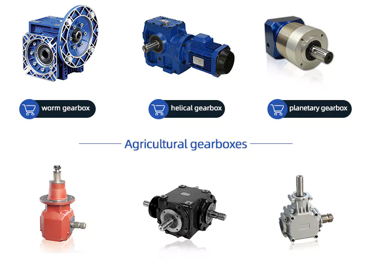
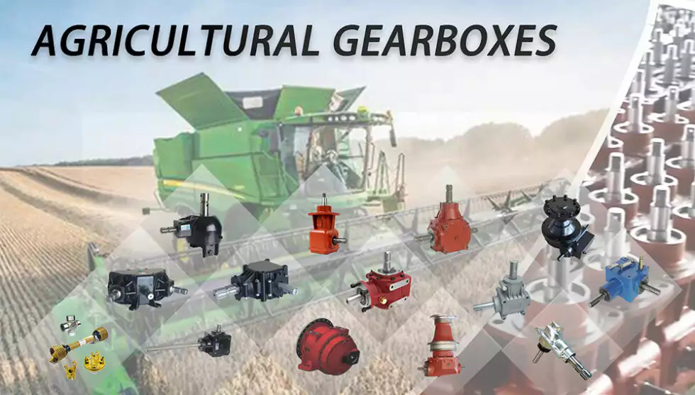
The agriculture industry uses gearboxes to implement a variety of processes. They are used in tractors, pumps, and agricultural machinery. The automotive industry uses gears in automobiles, but they are also found in mining and tea processing machinery. Industrial gearboxes also play an important role in feed and speed drives. The gearbox industry has a diverse portfolio of manufacturers and suppliers. Here are some examples of gearboxes:
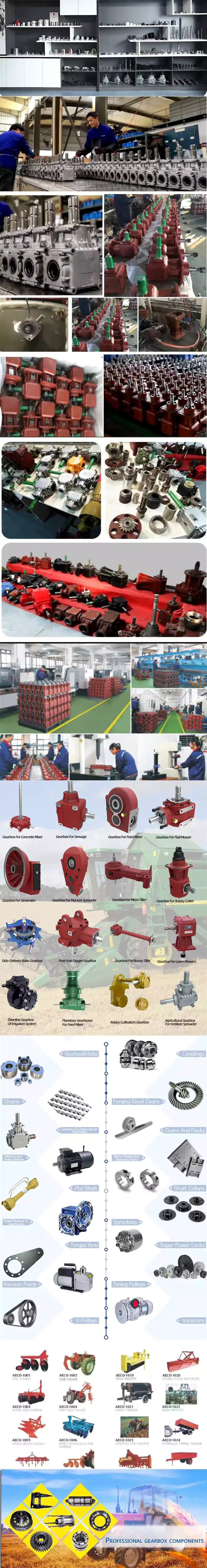
Gearboxes are complex pieces of equipment. They must be used properly to optimize efficiency and extend their lifespan. Manufacturers employ advanced technology and strict quality control processes to ensure their products meet the highest standards. In addition to manufacturing precision and reliability, gearbox manufacturers ensure that their products are safe for use in the production of industrial machinery. They are also used in office machines and medical equipment. However, the automotive gearbox market is becoming increasingly competitive.


editor by Cx 2023-07-04