Tag Archives: tractor farm for sale

China Buy Used Massey Ferguson Agricultural Farm Tractor 390 Model Available For Sell MF390 Tractor For Sale SHIPPING FROM FRANCE agricultural gearbox equipment

Condition: Utilized
Warranty: 3 years
Applicable Industries: Creating Material Shops, Manufacturing Plant, Farms, Design works , Other
Excess weight (KG): twenty five Exhaust Filter For CZPT RA5710 Vacuum Pump Oil Mist Separator Filter Factor 1200,1300 adjustableR Wheet Tread(mm)960-1300 unlimited adjustableWheet Base(mm)1750Minimum Land Clearance(mm)330(340)Gear Shifts8F+2RTyre Sizenine.5–24/650–16(9.5-24/550-sixteen)

gearbox

What Is a Gearbox?

There are several factors to consider when choosing a gearbox. Backlash, for example, is a consideration, as it is the angle at which the output shaft can rotate without the input shaft moving. While this isn’t necessary in applications without load reversals, it is important for precision applications involving load reversals. Examples of these applications include automation and robotics. If backlash is a concern, you may want to look at other factors, such as the number of teeth in each gear.

Function of a gearbox

A gearbox is a mechanical unit that consists of a chain or set of gears. The gears are mounted on a shaft and are supported by rolling element bearings. These devices alter the speed or torque of the machine they are used in. Gearboxes can be used for a wide variety of applications. Here are some examples of how gearboxes function. Read on to discover more about the gears that make up a gearbox.
Regardless of the type of transmission, most gearboxes are equipped with a secondary gear and a primary one. While the gear ratios are the same for both the primary and secondary transmission, the gearboxes may differ in size and efficiency. High-performance racing cars typically employ a gearbox with two green and one blue gear. Gearboxes are often mounted in the front or rear of the engine.
The primary function of a gearbox is to transfer torque from one shaft to another. The ratio of the driving gear’s teeth to the receiving member determines how much torque is transmitted. A large gear ratio will cause the main shaft to revolve at a slower speed and have a high torque compared to its counter shaft. Conversely, a low gear ratio will allow the vehicle to turn at a lower speed and produce a lower torque.
A conventional gearbox has input and output gears. The countershaft is connected to a universal shaft. The input and output gears are arranged to match the speed and torque of each other. The gear ratio determines how fast a car can go and how much torque it can generate. Most conventional transmissions use four gear ratios, with one reverse gear. Some have two shafts and three inputs. However, if the gear ratios are high, the engine will experience a loss of torque.
In the study of gearbox performance, a large amount of data has been collected. A highly ambitious segmentation process has yielded nearly 20,000 feature vectors. These results are the most detailed and comprehensive of all the available data. This research has a dual curse – the first is the large volume of data collected for the purpose of characterization, while the second is the high dimensionality. The latter is a complication that arises when the experimental gearbox is not designed to perform well.
gearbox

Bzvacklash

The main function of a gearhead is to multiply a moment of force and create a mechanical advantage. However, backlash can cause a variety of issues for the system, including impaired positioning accuracy and lowered overall performance. A zero backlash gearbox can eliminate motion losses caused by backlash and improve overall system performance. Here are some common problems associated with backlash in gearheads and how to fix them. After you understand how to fix gearbox backlash, you’ll be able to design a machine that meets your requirements.
To reduce gearbox backlash, many designers try to decrease the center distance of the gears. This eliminates space for lubrication and promotes excessive tooth mesh, which leads to premature mesh failure. To minimize gearbox backlash, a gear manufacturer may separate the two parts of the gear and adjust the mesh center distance between them. To do this, rotate one gear with respect to the fixed gear, while adjusting the other gear’s effective tooth thickness.
Several manufacturing processes may introduce errors, and reducing tooth thickness will minimize this error. Gears with bevel teeth are a prime example of this. This type of gear features a small number of teeth in comparison to its mating gear. In addition to reducing tooth thickness, bevel gears also reduce backlash. While bevel gears have fewer teeth than their mating gear, all of their backlash allowance is applied to the larger gear.
A gear’s backlash can affect the efficiency of a gearbox. In an ideal gear, the backlash is zero. But if there is too much, backlash can cause damage to the gears and cause it to malfunction. Therefore, the goal of gearbox backlash is to minimize this problem. However, this may require the use of a micrometer. To determine how much gearbox backlash you need, you can use a dial gauge or feeler gauge.
If you’ve been looking for a way to reduce backlash, a gearbox’s backlash may be the answer. However, backlash is not a revolt against the manufacturer. It is an error in motion that occurs naturally in gear systems that change direction. If it is left unaccounted for, it can lead to major gear degradation and even compromise the entire system. In this article, we’ll explain how backlash affects gears and how it affects the performance of a gearbox.

Design

The design of gearboxes consists of a variety of factors, including the type of material used, power requirements, speed and reduction ratio, and the application for which the unit is intended. The process of designing a gearbox usually begins with a description of the machine or gearbox and its intended use. Other key parameters to consider during gearbox design include the size and weight of the gear, its overall gear ratio and number of reductions, as well as the lubrication methods used.
During the design process, the customer and supplier will participate in various design reviews. These include concept or initial design review, manufacturing design validation, critical design review, and final design review. The customer may also initiate the process by initiating a DFMEA. After receiving the initial design approval, the design will go through several iterations before the finalized design is frozen. In some cases, the customer will require a DFMEA of the gearbox.
The speed increaser gearboxes also require special design considerations. These gearboxes typically operate at high speeds, causing problems with gear dynamics. Furthermore, the high speeds of the unit increase frictional and drag forces. A proper design of this component should minimize the effect of these forces. To solve these problems, a gearbox should incorporate a brake system. In some cases, an external force may also increase frictional forces.
Various types of gear arrangements are used in gearboxes. The design of the teeth of the gears plays a significant role in defining the type of gear arrangement in the gearbox. Spur gear is an example of a gear arrangement, which has teeth that run parallel to the axis of rotation. These gears offer high gear ratios and are often used in multiple stages. So, it is possible to create a gearbox that meets the needs of your application.
The design of gearboxes is the most complex process in the engineering process. These complex devices are made of multiple types of gears and are mounted on shafts. They are supported by rolling element bearings and are used for a variety of applications. In general, a gearbox is used to reduce speed and torque and change direction. Gearboxes are commonly used in motor vehicles, but can also be found in pedal bicycles and fixed machines.
gearbox

Manufacturers

There are several major segments in the gearbox market, including industrial, mining, and automotive. Gearbox manufacturers are required to understand the application and user industries to design a gearbox that meets their specific requirements. Basic knowledge of metallurgy is necessary. Multinational companies also provide gearbox solutions for the power generation industry, shipping industry, and automotive industries. To make their products more competitive, they need to focus on product innovation, geographical expansion, and customer retention.
The CZPT Group started as a small company in 1976. Since then, it has become a global reference in mechanical transmissions. Its production range includes gears, reduction gearboxes, and geared motors. The company was the first in Italy to achieve ISO certification, and it continues to grow into one of the world’s leading manufacturers of production gearboxes. As the industry evolves, CZPT focuses on research and development to create better products.
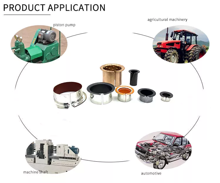
The agriculture industry uses gearboxes to implement a variety of processes. They are used in tractors, pumps, and agricultural machinery. The automotive industry uses gears in automobiles, but they are also found in mining and tea processing machinery. Industrial gearboxes also play an important role in feed and speed drives. The gearbox industry has a diverse portfolio of manufacturers and suppliers. Here are some examples of gearboxes:
Gearboxes are complex pieces of equipment. They must be used properly to optimize efficiency and extend their lifespan. Manufacturers employ advanced technology and strict quality control processes to ensure their products meet the highest standards. In addition to manufacturing precision and reliability, gearbox manufacturers ensure that their products are safe for use in the production of industrial machinery. They are also used in office machines and medical equipment. However, the automotive gearbox market is becoming increasingly competitive.

China Buy Used Massey Ferguson Agricultural Farm Tractor 390 Model Available For Sell MF390 Tractor For Sale SHIPPING FROM FRANCE     agricultural gearbox equipment	China Buy Used Massey Ferguson Agricultural Farm Tractor 390 Model Available For Sell MF390 Tractor For Sale SHIPPING FROM FRANCE     agricultural gearbox equipment
editor by Cx 2023-07-04

China high quality Farm 20-25HP 3 Point Hitch Mini Tractor Flail Mower Pto Drive Mower for Sale with Great quality

Product Description

MODEL EF85 EF95 EF105 EF115 EF125
Structure Weight 133kg 145kg 151kg 158kg 165kg
Working Width 829mm 929mm 1571mm 1129mm 1229mm
PTO Turning Speed 540r/min 540r/min 540r/min 540r/min 540r/min
Flail Type Hammer/Y Blade
Number of Flail Hammer 12 /Y Blade 24 Hammer 18 /Y Blade 36 Hammer 18 /Y Blade 36 Hammer 18 /Y Blade 36 Hammer 18 /Y Blade 36
Tractor HP 14-18hp 16-20hp 20-30hp 20-30hp 25-35hp


MODEL EF135 EF145 EF155 EF165 EF175
Structure Weight 175kg 178kg 182kg 190kg 198kg
Working Width 1329mm 1429mm 1529mm 1629mm 1729mm
PTO Turning Speed 540r/min 540r/min 540r/min 540r/min 540r/min
Flail Type Y Blade/Hammer
Number of Flail Hammer 24 /Y Blade48 Hammer 24 /Y Blade48 Hammer 24 /Y Blade48 Hammer 24 /Y Blade48 Hammer 30 /Y Blade 60
Tractor HP 25-35hp 25-35hp 30-40hp 30-40hp 30-40hp

Perfect for use after storms when debris is scattered throughout areas usually maintained with normal mowers~ Multi-purpose machines for mulching sticks~ Ideal for thick grass, sticks, undergrowth and light vine mulching~ Vegetable & pasture topping~ Roadside maintenance.

HangZhou Qianyi Machinery Technology Co.,Ltd existing staff 50 people, in 2571 passed the ISO9001 quality system certification and passed CE certification.

Accumulated after years of development, we have many advanced equipment, like Germany fast Trulaser3030 laser cutting ,machine, CNC punch press TruPunch1000, CNC shearing machine, CNC lathe, bending machine, seam welding machine and more than 1 formula 1-160-1 high-end mechanical production equipment.

We provide good design, to help customers reduce costs of development and improve production efficiency. With complete testing equipment, strict quality control and abundant technical force, our machines are mainly exported to European, North American and Southeast Asian countries.

All of our machines are with 1 year warranty. We often insist on 1 principle”Better quality!Better service!Better price!”

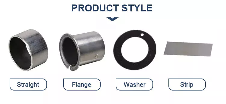
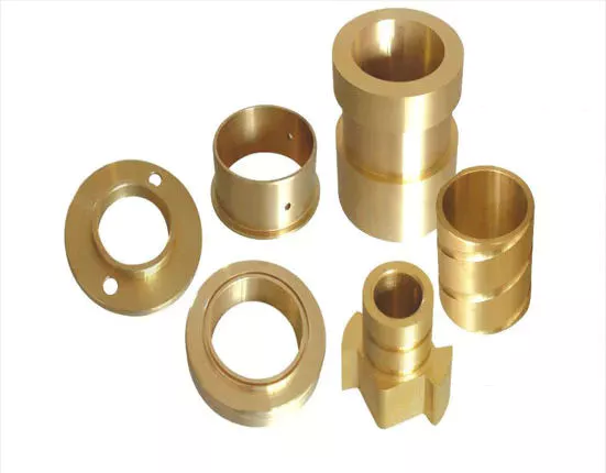
What is the purpose of the bushing?

If you notice the truck making noises when cornering, the bushings may be worn. You may need to replace the ball joint or stabilizer bar, but a simple inspection will reveal that the noise is coming from the bushing. The noise from a worn bushing on a metal joint can mimic the sound of other problems in the suspension, such as a loose stabilizer bar or a failed ball joint.
bushing

Function

What is the purpose of the bushing? They play an important role in the operation of various mechanical parts. Their main functions include reducing the clearance between the shaft and the bearing and reducing the leakage of the valve. Bushings are used in different ways to ensure smooth operation and longevity. However, some new designers don’t appreciate the functionality of the case. So let’s discuss these features. Some of their most common applications are listed below.
First, the shell does a lot of things. They reduce noise, control vibration, and provide amazing protection for all kinds of industrial equipment. Large industrial equipment faces more wear, vibration and noise, which can render it completely inoperable. Bushings help prevent this by reducing noise and vibration. Bushing sets also extend equipment life and improve its performance. Therefore, you should not underestimate the importance of the casing in your device.
Another common function of bushings is to support components during assembly. In other words, the bushing reduces the risk of machine wear. In addition to this, they are superior to bearings, which are notoriously expensive to maintain. However, they are still useful, and their versatility cannot be overemphasized. If you’re considering installing one, you’ll be glad you did! These products have become a necessity in the modern industrial world. If you’re wondering how to choose one, here are some of the most common bushing uses.
Electrical bushings are an important part of many electrical equipment. They carry high voltage currents through the enclosure and provide an insulating barrier between live conductors and metal bodies at ground potential. They are made of a central conductive rod (usually copper or aluminum) and surrounding insulators made of composite resin silicone rubber. Additionally, the bushings are made of various materials. Whether copper, aluminum or plastic, they are an important part of many types of electrical equipment.

type

There are several different types of bushings on the market today. They may be cheap but they are of good quality. These products can be used in telephones, cable television, computer data lines and alarm systems. The key to buying these products online is finding the right appliance store and choosing a high-quality product. An online appliance store should have comprehensive information and ease of use. For the right electrical bushing, you should look for reliable online stores with the best prices and high quality products.
Capacitive grading bushings use conductive foils inserted into paper to stabilize the electric field and balance the internal energy of the bushing. The conductive foil acts as a capacitive element, connecting the high voltage conductor to ground. These types of bushings are sometimes referred to as capacitor grade bushings. Capacitive grading bushings are usually made of paper impregnated with epoxy resin or mineral oil.
When buying enclosures, you should know how they are used. Unlike ball bearings, bushings should be stored upright so that they are in the correct working position. This is because horizontal placement can cause air bubbles to form in the fill insulation. It is also important to store the bushing properly to prevent damage. The wrong way to store these components can result in costly repairs.
In addition to the physical structure, the bushing insulation must also be effective over the long term. It must resist partial discharge and working electric field stress. The material and design of the bushing can vary widely. Early on, porcelain-based materials were popular in bushing designs. Porcelain was chosen because of its low cost of production and very low linear expansion. Ceramic bushings, on the other hand, require a lot of metal fittings and flexible seals.
bushing

Durability

The RIG 3 Bushing Durability Test Standard simulates real-world service conditions for automotive bushings. This three-channel test standard varies casing loads and stresses by applying a range of different load conditions and various control factors. This test is critical to the durability of the case, as it accurately reproduces the dynamic loads that occur during normal use. This test is a key component of the automotive industry and is widely used in many industries.
The Advanced Casing Model has 5 modules to address asymmetry, nonlinearity, and hysteresis. This model also represents the CZPT lag model. The model can be parameterized in the time domain using MATLAB, and the results can be exported to other simulation software. The developed bushing model is a key component in the durability and performance of vehicle suspension components.
A conductive material is coated on the inner surface of the sleeve. The coating is chosen to conduct a certain amount of current. The conductive path extends from the blade spacer 126 to the sleeve projecting edge 204 and then through the housing 62 to the ground. The coating is made of a low friction material and acts as a wear surface against the bushing sidewall 212 and the housing 62 .
Another important factor in a bushing’s durability is its ability to friction. The higher the operating speed, the greater the load on the bushing. Since bushings are designed for lighter loads and slower speeds, they cannot handle large loads at high speeds. The P-max or V-max value of a bushing is its maximum load or speed at 0 rpm. The PV value must be lower than the manufacturer’s PV value.

price

If you need to replace the bushing on the control arm, you should understand the cost involved. This repair can be expensive, depending on the make and model of your car. Generally, you should pay between $105 and $180 for a replacement. However, you can choose to have it done by a mechanic at a lower cost. The labor cost for this job can be around $160, depending on your automaker.
The cost of replacing the control arm bushings can range from $200 on the low end to $500 on a luxury car. While parts are cheap, labor costs are the highest. Mechanics had to remove suspension and wheel assemblies to replace bushings. If you have some mechanical knowledge, you can replace the bushing yourself. Control arm bushings on the wheel side are usually about $20 each. Still, if you’re not a mechanic, you can save money by doing it yourself.
bushing

Install

Press-fit bushings are installed using a retaining ring with a diameter 0.3/0.4 mm larger than the inner diameter of the bushing. To ensure accurate installation, use a mechanically driven, pneumatic or hydraulic drill and insert the bushing into the appropriate hole. This process is best done using mounting holes with drilled holes for the clamps. Make sure the mounting hole is in the center of the bushing and free of debris.
Once the bushing is positioned, use a vise to install its nut. A cold bushing will compress and fit the shell better. Place the sleeve in the refrigerator for at least 24 hours to aid installation. After removing the bushing from the refrigerator, make sure it has enough diameter to fit into the enclosure. Next, place the opposite socket into the enclosure and use it as a stand. After a few minutes, the bushing should be fully seated in the housing.
Install the new bushing into the housing hole. If the previous 1 had a metal case, insert the new 1 through the taper. Always lubricate the inner and outer surfaces of the bushing. Then, apply pressure to the inner metal sleeve of the new bushing. You may notice that the new bushing does not exactly match the housing hole. However, that’s okay because the outer diameter of the bushing is larger than the outer diameter of the hub drive.
The installation of the bushing requires the use of the hydraulic unit 16 . Hydraulic unit 16 is located near the #1 journal of the camshaft and extends from #2 to #7. Hydraulic fluid forces piston 22 away from the outer end of cylinder 20 and pushes shaft 14 forward. The shaft is then moved forward, pushing the bushing 17 onto the piston. Multiple bushings can be installed in a single engine.

China high quality Farm 20-25HP 3 Point Hitch Mini Tractor Flail Mower Pto Drive Mower for Sale     with Great qualityChina high quality Farm 20-25HP 3 Point Hitch Mini Tractor Flail Mower Pto Drive Mower for Sale     with Great quality

China Hot selling Farm 20-25HP 3 Point Hitch Mini Tractor Flail Mower Pto Drive Mower for Sale with high quality

Product Description

MODEL AGF-140 AGF-160 AGF-180 AGF-200 AGF-220
Structure Weight 598kg 612kg 658kg 698kg 738kg
Cutting Width 1400mm 1600mm 1800mm 2000mm 2200mm
PTO Turnning Speed 540r/min 540r/min 540r/min 540r/min 540r/min
PTO Spline 6×8×1600mm 6×8×1600mm 6×8×1600mm 6×8×1600mm 6×8×1600mm
Tractor HP 40-85HP 50-85HP 55-90HP 55-90HP 55-90HP
Include PTO shaft

Model AGFK140 AGFK160 AGFK180 AGFK200 AGFK220
Cutting Width 1400mm 1600mm 1800mm 2000mm 2200mm
Reach Angle Up 90°
Reach Angle Down 55°
PTO 540r/min
Tractor HP 30-40HP 40-60HP 50-70HP 60-90HP

Q: Are you factory or trading company?
A) We are ISO9001 certified factory, mainly manufacture in Forestry & Farm Machinery.
B) Using “Self-produced Self-marketing” business, reducing the cost of intermediate links.

Q: What’s your company advantages?
A) As the leading manufacturer of forest machines, we have exported to European market for more than 10 years, familiar with forest and farm market and can recommend to clients right products.
B) We have various products and can offer all the machines and tools in the forest and farm. You can get all the items you need. Easy and convenient for you.
C) With us your money and your business is safe. We can offer 7-days refund in case of bad quality.
D) Coming together is a beginning; keeping together is progress; working together is success.

Q: Can we buy 1 sample?
Yes, we need to add sample fee to the price and will return it back to your after receiving your large order in future.

Q: What’s your delivery time?
After receiving your payment, we start to produce your order. It usually takes about 15-45 days depending on the products you order.

Q: How do you control your quality?
To guarantee high quality and efficient management, we have passed ISO9001 quality management system certificate. All of our products are 100% inspected before shipment. Our whole manufacturing processes are under a very serious and strict system in our company.

Q: What’s your product warranty?
The warranty time of the machine is 1 year. During this period, we will send you the replacement for the broken part(not man made).
To meet the every demand of customer is our goal. We are standing by for any question of customer. We try to make our service fast, efficient and satisfied.

Q: What’s your company mainly exporting market?
We mainly export to European, North American, Australia, English and Southeast Asia Market. Because of good quality and service, we have establish good and long business relations with many clients. Welcome clients from all over the world to visit our factory.
 

Lead Screws and Clamp Style Collars

If you have a lead screw, you’re probably interested in learning about the Acme thread on this type of shaft. You might also be interested in finding out about the Clamp style collars and Ball screw nut. But before you buy a new screw, make sure you understand what the terminology means. Here are some examples of screw shafts:

Acme thread

The standard ACME thread on a screw shaft is made of a metal that is resistant to corrosion and wear. It is used in a variety of applications. An Acme thread is available in a variety of sizes and styles. General purpose Acme threads are not designed to handle external radial loads and are supported by a shaft bearing and linear guide. Their design is intended to minimize the risk of flank wedging, which can cause friction forces and wear. The Centralizing Acme thread standard caters to applications without radial support and allows the thread to come into contact before its flanks are exposed to radial loads.
The ACME thread was first developed in 1894 for machine tools. While the acme lead screw is still the most popular screw in the US, European machines use the Trapezoidal Thread (Metric Acme). The acme thread is a stronger and more resilient alternative to square threads. It is also easier to cut than square threads and can be cut by using a single-point threading die.
Similarly to the internal threads, the metric versions of Acme are similar to their American counterparts. The only difference is that the metric threads are generally wider and are used more frequently in industrial settings. However, the metric-based screw threads are more common than their American counterparts worldwide. In addition, the Acme thread on screw shafts is used most often on external gears. But there is still a small minority of screw shafts that are made with a metric thread.
ACME screws provide a variety of advantages to users, including self-lubrication and reduced wear and tear. They are also ideal for vertical applications, where a reduced frictional force is required. In addition, ACME screws are highly resistant to back-drive and minimize the risk of backlash. Furthermore, they can be easily checked with readily available thread gauges. So, if you’re looking for a quality ACME screw for your next industrial project, look no further than ACME.
screwshaft

Lead screw coatings

The properties of lead screw materials affect their efficiency. These materials have high anti-corrosion, thermal resistance, and self-lubrication properties, which eliminates the need for lubrication. These coating materials include polytetrafluoroethylene (PFE), polyether ether ketone (PEK), and Vespel. Other desirable properties include high tensile strength, corrosion resistance, and rigidity.
The most common materials for lead screws are carbon steel, stainless steel, and aluminum. Lead screw coatings can be PTFE-based to withstand harsh environments and remove oil and grease. In addition to preventing corrosion, lead screw coatings improve the life of polymer parts. Lead screw assembly manufacturers offer a variety of customization options for their lead screw, including custom-molded nuts, thread forms, and nut bodies.
Lead screws are typically measured in rpm, or revolutions per minute. The PV curve represents the inverse relationship between contact surface pressure and sliding velocity. This value is affected by the material used in the construction of the screw, lubrication conditions, and end fixity. The critical speed of lead screws is determined by their length and minor diameter. End fixity refers to the support for the screw and affects its rigidity and critical speed.
The primary purpose of lead screws is to enable smooth movement. To achieve this, lead screws are usually preloaded with axial load, enabling consistent contact between a screw’s filets and nuts. Lead screws are often used in linear motion control systems and feature a large area of sliding contact between male and female threads. Lead screws can be manually operated or mortised and are available in a variety of sizes and materials. The materials used for lead screws include stainless steel and bronze, which are often protected by a PTFE type coating.
These screws are made of various materials, including stainless steel, bronze, and various plastics. They are also made to meet specific requirements for environmental conditions. In addition to lead screws, they can be made of stainless steel, aluminum, and carbon steel. Surface coatings can improve the screw’s corrosion resistance, while making it more wear resistant in tough environments. A screw that is coated with PTFE will maintain its anti-corrosion properties even in tough environments.
screwshaft

Clamp style collars

The screw shaft clamp style collar is a basic machine component, which is attached to the shaft via multiple screws. These collars act as mechanical stops, load bearing faces, or load transfer points. Their simple design makes them easy to install. This article will discuss the pros and cons of this style of collar. Let’s look at what you need to know before choosing a screw shaft clamp style collar. Here are some things to keep in mind.
Clamp-style shaft collars are a versatile mounting option for shafts. They have a recessed screw that fully engages the thread for secure locking. Screw shaft clamp collars come in different styles and can be used in both drive and power transmission applications. Listed below are the main differences between these 2 styles of collars. They are compatible with all types of shafts and are able to handle axial loads of up to 5500 pounds.
Clamp-style shaft collars are designed to prevent the screw from accidentally damaging the shaft when tightened. They can be tightened with a set screw to counteract the initial clamping force and prevent the shaft from coming loose. However, when tightening the screw, you should use a torque wrench. Using a set screw to tighten a screw shaft collar can cause it to warp and reduce the surface area that contacts the shaft.
Another key advantage to Clamp-style shaft collars is that they are easy to install. Clamp-style collars are available in one-piece and two-piece designs. These collars lock around the shaft and are easy to remove and install. They are ideal for virtually any shaft and can be installed without removing any components. This type of collar is also recommended for those who work on machines with sensitive components. However, be aware that the higher the OD, the more difficult it is to install and remove the collar.
Screw shaft clamp style collars are usually one-piece. A two-piece collar is easier to install than a one-piece one. The two-piece collars provide a more effective clamping force, as they use the full seating torque. Two-piece collars have the added benefit of being easy to install because they require no tools to install. You can disassemble one-piece collars before installing a two-piece collar.
screwshaft

Ball screw nut

The proper installation of a ball screw nut requires that the nut be installed on the center of the screw shaft. The return tubes of the ball nut must be oriented upward so that the ball nut will not overtravel. The adjusting nut must be tightened against a spacer or spring washer, then the nut is placed on the screw shaft. The nut should be rotated several times in both directions to ensure that it is centered.
Ball screw nuts are typically manufactured with a wide range of preloads. Large preloads are used to increase the rigidity of a ball screw assembly and prevent backlash, the lost motion caused by a clearance between the ball and nut. Using a large amount of preload can lead to excessive heat generation. The most common preload for ball screw nuts is 1 to 3%. This is usually more than enough to prevent backlash, but a higher preload will increase torque requirements.
The diameter of a ball screw is measured from its center, called the ball circle diameter. This diameter represents the distance a ball will travel during 1 rotation of the screw shaft. A smaller diameter means that there are fewer balls to carry the load. Larger leads mean longer travels per revolution and higher speeds. However, this type of screw cannot carry a greater load capacity. Increasing the length of the ball nut is not practical, due to manufacturing constraints.
The most important component of a ball screw is a ball bearing. This prevents excessive friction between the ball and the nut, which is common in lead-screw and nut combinations. Some ball screws feature preloaded balls, which avoid “wiggle” between the nut and the ball. This is particularly desirable in applications with rapidly changing loads. When this is not possible, the ball screw will experience significant backlash.
A ball screw nut can be either single or multiple circuits. Single or multiple-circuit ball nuts can be configured with 1 or 2 independent closed paths. Multi-circuit ball nuts have 2 or more circuits, making them more suitable for heavier loads. Depending on the application, a ball screw nut can be used for small clearance assemblies and compact sizes. In some cases, end caps and deflectors may be used to feed the balls back to their original position.

China Hot selling Farm 20-25HP 3 Point Hitch Mini Tractor Flail Mower Pto Drive Mower for Sale     with high qualityChina Hot selling Farm 20-25HP 3 Point Hitch Mini Tractor Flail Mower Pto Drive Mower for Sale     with high quality

China best Farm Tractor 3 Point Linkage Pto Drive Mounted Rear Tow Behind Finishing Mower for Sale near me supplier

Product Description

MODEL AGF-140 AGF-160 AGF-180 AGF-200 AGF-220
Structure Weight 598kg 612kg 658kg 698kg 738kg
Cutting Width 1400mm 1600mm 1800mm 2000mm 2200mm
PTO Turnning Speed 540r/min 540r/min 540r/min 540r/min 540r/min
PTO Spline 6×8×1600mm 6×8×1600mm 6×8×1600mm 6×8×1600mm 6×8×1600mm
Tractor HP 40-85HP 50-85HP 55-90HP 55-90HP 55-90HP
Include PTO shaft

Model AGFK140 AGFK160 AGFK180 AGFK200 AGFK220
Cutting Width 1400mm 1600mm 1800mm 2000mm 2200mm
Reach Angle Up 90°
Reach Angle Down 55°
PTO 540r/min
Tractor HP 30-40HP 40-60HP 50-70HP 60-90HP

Q: Are you factory or trading company?
A) We are ISO9001 certified factory, mainly manufacture in Forestry & Farm Machinery.
B) Using “Self-produced Self-marketing” business, reducing the cost of intermediate links.

Q: What’s your company advantages?
A) As the leading manufacturer of forest machines, we have exported to European market for more than 10 years, familiar with forest and farm market and can recommend to clients right products.
B) We have various products and can offer all the machines and tools in the forest and farm. You can get all the items you need. Easy and convenient for you.
C) With us your money and your business is safe. We can offer 7-days refund in case of bad quality.
D) Coming together is a beginning; keeping together is progress; working together is success.

Q: Can we buy 1 sample?
Yes, we need to add sample fee to the price and will return it back to your after receiving your large order in future.

Q: What’s your delivery time?
After receiving your payment, we start to produce your order. It usually takes about 15-45 days depending on the products you order.

Q: How do you control your quality?
To guarantee high quality and efficient management, we have passed ISO9001 quality management system certificate. All of our products are 100% inspected before shipment. Our whole manufacturing processes are under a very serious and strict system in our company.

Q: What’s your product warranty?
The warranty time of the machine is 1 year. During this period, we will send you the replacement for the broken part(not man made).
To meet the every demand of customer is our goal. We are standing by for any question of customer. We try to make our service fast, efficient and satisfied.

Q: What’s your company mainly exporting market?
We mainly export to European, North American, Australia, English and Southeast Asia Market. Because of good quality and service, we have establish good and long business relations with many clients. Welcome clients from all over the world to visit our factory.
 

Screw Shaft Features Explained

When choosing the screw shaft for your application, you should consider the features of the screws: threads, lead, pitch, helix angle, and more. You may be wondering what these features mean and how they affect the screw’s performance. This article explains the differences between these factors. The following are the features that affect the performance of screws and their properties. You can use these to make an informed decision and purchase the right screw. You can learn more about these features by reading the following articles.

Threads

The major diameter of a screw thread is the larger of the 2 extreme diameters. The major diameter of a screw is also known as the outside diameter. This dimension can’t be directly measured, but can be determined by measuring the distance between adjacent sides of the thread. In addition, the mean area of a screw thread is known as the pitch. The diameter of the thread and pitch line are directly proportional to the overall size of the screw.
The threads are classified by the diameter and pitch. The major diameter of a screw shaft has the largest number of threads; the smaller diameter is called the minor diameter. The thread angle, also known as the helix angle, is measured perpendicular to the axis of the screw. The major diameter is the largest part of the screw; the minor diameter is the lower end of the screw. The thread angle is the half distance between the major and minor diameters. The minor diameter is the outer surface of the screw, while the top surface corresponds to the major diameter.
The pitch is measured at the crest of a thread. In other words, a 16-pitch thread has a diameter of 1 sixteenth of the screw shaft’s diameter. The actual diameter is 0.03125 inches. Moreover, a large number of manufacturers use this measurement to determine the thread pitch. The pitch diameter is a critical factor in successful mating of male and female threads. So, when determining the pitch diameter, you need to check the thread pitch plate of a screw.
screwshaft

Lead

In screw shaft applications, a solid, corrosion-resistant material is an important requirement. Lead screws are a robust choice, which ensure shaft direction accuracy. This material is widely used in lathes and measuring instruments. They have black oxide coatings and are suited for environments where rusting is not acceptable. These screws are also relatively inexpensive. Here are some advantages of lead screws. They are highly durable, cost-effective, and offer high reliability.
A lead screw system may have multiple starts, or threads that run parallel to each other. The lead is the distance the nut travels along the shaft during a single revolution. The smaller the lead, the tighter the thread. The lead can also be expressed as the pitch, which is the distance between adjacent thread crests or troughs. A lead screw has a smaller pitch than a nut, and the smaller the lead, the greater its linear speed.
When choosing lead screws, the critical speed is the maximum number of revolutions per minute. This is determined by the minor diameter of the shaft and its length. The critical speed should never be exceeded or the lead will become distorted or cracked. The recommended operational speed is around 80 percent of the evaluated critical speed. Moreover, the lead screw must be properly aligned to avoid excessive vibrations. In addition, the screw pitch must be within the design tolerance of the shaft.

Pitch

The pitch of a screw shaft can be viewed as the distance between the crest of a thread and the surface where the threads meet. In mathematics, the pitch is equivalent to the length of 1 wavelength. The pitch of a screw shaft also relates to the diameter of the threads. In the following, the pitch of a screw is explained. It is important to note that the pitch of a screw is not a metric measurement. In the following, we will define the 2 terms and discuss how they relate to 1 another.
A screw’s pitch is not the same in all countries. The United Kingdom, Canada, and the United States have standardized screw threads according to the UN system. Therefore, there is a need to specify the pitch of a screw shaft when a screw is being manufactured. The standardization of pitch and diameter has also reduced the cost of screw manufacturing. Nevertheless, screw threads are still expensive. The United Kingdom, Canada, and the United States have introduced a system for the calculation of screw pitch.
The pitch of a lead screw is the same as that of a lead screw. The diameter is 0.25 inches and the circumference is 0.79 inches. When calculating the mechanical advantage of a screw, divide the diameter by its pitch. The larger the pitch, the more threads the screw has, increasing its critical speed and stiffness. The pitch of a screw shaft is also proportional to the number of starts in the shaft.

Helix angle

The helix angle of a screw shaft is the angle formed between the circumference of the cylinder and its helix. Both of these angles must be equal to 90 degrees. The larger the lead angle, the smaller the helix angle. Some reference materials refer to angle B as the helix angle. However, the actual angle is derived from calculating the screw geometry. Read on for more information. Listed below are some of the differences between helix angles and lead angles.
High helix screws have a long lead. This length reduces the number of effective turns of the screw. Because of this, fine pitch screws are usually used for small movements. A typical example is a 16-mm x 5-inch screw. Another example of a fine pitch screw is a 12x2mm screw. It is used for small moves. This type of screw has a lower lead angle than a high-helix screw.
A screw’s helix angle refers to the relative angle of the flight of the helix to the plane of the screw axis. While screw helix angles are not often altered from the standard square pitch, they can have an effect on processing. Changing the helix angle is more common in two-stage screws, special mixing screws, and metering screws. When a screw is designed for this function, it should be able to handle the materials it is made of.
screwshaft

Size

The diameter of a screw is its diameter, measured from the head to the shaft. Screw diameters are standardized by the American Society of Mechanical Engineers. The diameters of screws range from 3/50 inches to 16 inches, and more recently, fractions of an inch have been added. However, shaft diameters may vary depending on the job, so it is important to know the right size for the job. The size chart below shows the common sizes for screws.
Screws are generally referred to by their gauge, which is the major diameter. Screws with a major diameter less than a quarter of an inch are usually labeled as #0 to #14 and larger screws are labeled as sizes in fractions of an inch. There are also decimal equivalents of each screw size. These measurements will help you choose the correct size for your project. The screws with the smaller diameters were not tested.
In the previous section, we described the different shaft sizes and their specifications. These screw sizes are usually indicated by fractions of an inch, followed by a number of threads per inch. For example, a ten-inch screw has a shaft size of 2” with a thread pitch of 1/4″, and it has a diameter of 2 inches. This screw is welded to a two-inch Sch. 40 pipe. Alternatively, it can be welded to a 9-inch O.A.L. pipe.
screwshaft

Shape

Screws come in a wide variety of sizes and shapes, from the size of a quarter to the diameter of a U.S. quarter. Screws’ main function is to hold objects together and to translate torque into linear force. The shape of a screw shaft, if it is round, is the primary characteristic used to define its use. The following chart shows how the screw shaft differs from a quarter:
The shape of a screw shaft is determined by 2 features: its major diameter, or distance from the outer edge of the thread on 1 side to the inner smooth surface of the shaft. These are generally 2 to 16 millimeters in diameter. Screw shafts can have either a fully threaded shank or a half-threaded shank, with the latter providing better stability. Regardless of whether the screw shaft is round or domed, it is important to understand the different characteristics of a screw before attempting to install it into a project.
The screw shaft’s diameter is also important to its application. The ball circle diameter refers to the distance between the center of 2 opposite balls in contact with the grooves. The root diameter, on the other hand, refers to the distance between the bottommost grooves of the screw shaft. These are the 2 main measurements that define the screw’s overall size. Pitch and nominal diameter are important measurements for a screw’s performance in a particular application.

Lubrication

In most cases, lubrication of a screw shaft is accomplished with grease. Grease is made up of mineral or synthetic oil, thickening agent, and additives. The thickening agent can be a variety of different substances, including lithium, bentonite, aluminum, and barium complexes. A common classification for lubricating grease is NLGI Grade. While this may not be necessary when specifying the type of grease to use for a particular application, it is a useful qualitative measure.
When selecting a lubricant for a screw shaft, the operating temperature and the speed of the shaft determine the type of oil to use. Too much oil can result in heat buildup, while too little can lead to excessive wear and friction. The proper lubrication of a screw shaft directly affects the temperature rise of a ball screw, and the life of the assembly. To ensure the proper lubrication, follow the guidelines below.
Ideally, a low lubrication level is appropriate for medium-sized feed stuff factories. High lubrication level is appropriate for larger feed stuff factories. However, in low-speed applications, the lubrication level should be sufficiently high to ensure that the screws run freely. This is the only way to reduce friction and ensure the longest life possible. Lubrication of screw shafts is an important consideration for any screw.

China best Farm Tractor 3 Point Linkage Pto Drive Mounted Rear Tow Behind Finishing Mower for Sale     near me supplier China best Farm Tractor 3 Point Linkage Pto Drive Mounted Rear Tow Behind Finishing Mower for Sale     near me supplier