Tag Archives: tractor hitch

China Standard 3 Point Hitch Mounted Flail Mower for Tractor Mower with high quality

Product Description

Flail Mower

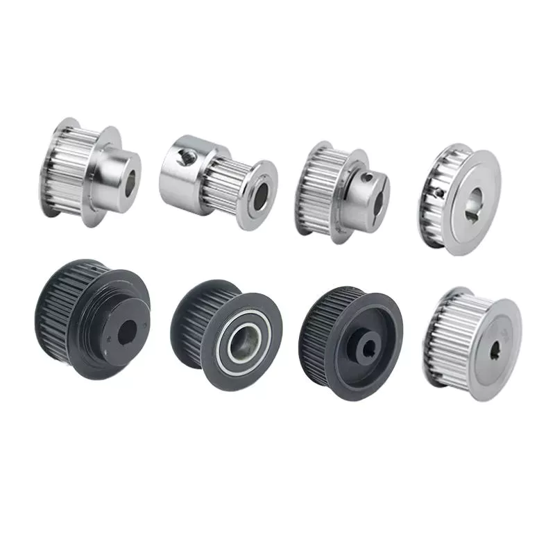
    1. Transmission: By sturdy toothed belts.
    2. Gearbox is made of gravity casting iron. Material performance is better. Not easy broken.
    3. With adjustable rear roller, the mowing height can be adjusted.
    4. The structure is firm and stable.
    5.  High welding processes
    6.  With front protection, it can prevent splashing.
    7. Y shape blades, hammer and vertical blades for grass. With double blades.
    8. Cat. I universal three-point hitch cardan shaft.


Model

EFD-95 EFD-105 EFD-115 EFD-125 EFD-135
Dimension(mm) 1040×700×520 1140×700×520 1240*700*520 1340×700×520 1440×700×520
Weight(Kg) 130 KG 145Kg 155KG 170Kg 175Kg
Cutting Width 950mm 1050mm 1150mm 1250mm 1350mm
 PTO Input Speed 540r/min 540r/min 540r/min 540r/min 540r/min
Y shape blades 60 72 78 84 84
Power Required 16-20HP 20-25HP 20-30HP 20-30HP 20-30HP
3 point linkage  Cat.1 Cat.1  Cat.1 Cat.1 Cat.1
Packing size(mm) 1150×750×550 1250×750×550 1350*750*550 1450×750×550 1550×750×550

Company Profile

HangZhou CZPT Industry & Trade Co., Ltd., is a professional manufacturer and exporter of whole set of agriculture machines and garden tools. Our company was established since 2003 with Hanma Industry Company.

Our main products include rotovator, flail mower, finishing mower, CZPT mower, wood chipper, plow, cultivator, potato harvester/ planter and Japanese tractor parts, etc. Due to our super International quality standard and rapid & excellent after-sales service, CZPT machines are greatly popular in various markets around the world, and already reached to Europe, North America, South America, Australia, almost covers 80 countries in World.

LEFA always believe that we will take better farming life to you by top-quality laser cutting machine & CNC bending machine & professional paint-spraying & strong welding.

PROFESSIONAL PRODUCTION:

1.Professional team with rich experience

2.Powerful factory strength with CE certification

3.Best after-sales service
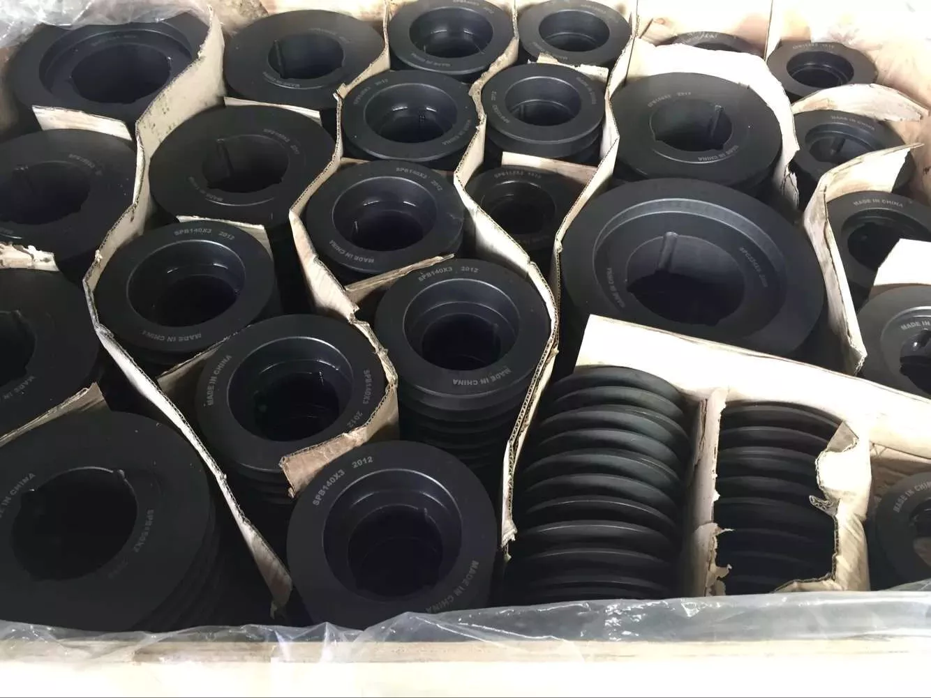
 

Packing & Shipping

Packaging Detail: Iron pallet or wooden cases
Delivery Detail: By sea or By air

1. Waterproof packing with the international export standard by 20ft, 40ftcontainer.
Wooden Case or Iron Pallet.
2. The whole set of machines size are large as normal, so we will use Waterproof materials to pack
all of them. The motor, gear box or other easily damaged parts, we will put them into box. 

We have a professional shipping department, they will try their best to save your container quantity.

Machine videos in YOUTOBE

          EFDL SIDE MOWERS

         EFGL SIDE MOWERS

          FM FINISHING MOWERS

        TM CZPT MOWERS

            RT ROTARY TILLERS

https://youtu.be/d3H1-yXUImc                                 AP-90 POTATO HARVESTER

https://youtu.be/AAkgnV_bY80                        LF-PT32 POTATO PLANTER

https://youtu.be/66geQQOUTLY                        wood chipper BX-42

https://youtu.be/iIVOwCTCl_c                       HAY BALER

FAQ:
Q1. How to buy 3 point rotary tiller?
Inquiry ———> Quotation ——–>Price reasonable ——->Check with specification —–>Proforma Invoice sent ————>Payment made ——-> Producing the items ——->Product shipment ———–> Customer confirm

Q2.How long is the delivery date for agriculture machinery cultivator?
A:In general, we can ship the goods within 30-45 days after receiving your payment. Of course, it also depends on your quantity.

Q3. How can I get to your factory to buy tractor cultivator?
A:We are located in HangZhou, only 1 hour’s distance to ZheJiang or HangZhou. You can fly to ZheJiang /HangZhou/HangZhou Airport , the transportation is very convenient

Q4.Do you have stock for rotary tiller?
A:In general, we have some stock, while if you need a bulk order, we still need time to produce it. Of course, we will inform all details you before your payment.

Q5: What’s your main products?
A: Our products are covered almost all farm machines and Japanese tractors parts, we can meet your any demands.

Q6. What is your terms of payment?
A: T/T, L/C, Paypal, Western Union
 

How to Select a Worm Shaft and Gear For Your Project

You will learn about axial pitch PX and tooth parameters for a Worm Shaft 20 and Gear 22. Detailed information on these 2 components will help you select a suitable Worm Shaft. Read on to learn more….and get your hands on the most advanced gearbox ever created! Here are some tips for selecting a Worm Shaft and Gear for your project!…and a few things to keep in mind.
worm shaft

Gear 22

The tooth profile of Gear 22 on Worm Shaft 20 differs from that of a conventional gear. This is because the teeth of Gear 22 are concave, allowing for better interaction with the threads of the worm shaft 20. The worm’s lead angle causes the worm to self-lock, preventing reverse motion. However, this self-locking mechanism is not entirely dependable. Worm gears are used in numerous industrial applications, from elevators to fishing reels and automotive power steering.
The new gear is installed on a shaft that is secured in an oil seal. To install a new gear, you first need to remove the old gear. Next, you need to unscrew the 2 bolts that hold the gear onto the shaft. Next, you should remove the bearing carrier from the output shaft. Once the worm gear is removed, you need to unscrew the retaining ring. After that, install the bearing cones and the shaft spacer. Make sure that the shaft is tightened properly, but do not over-tighten the plug.
To prevent premature failures, use the right lubricant for the type of worm gear. A high viscosity oil is required for the sliding action of worm gears. In two-thirds of applications, lubricants were insufficient. If the worm is lightly loaded, a low-viscosity oil may be sufficient. Otherwise, a high-viscosity oil is necessary to keep the worm gears in good condition.
Another option is to vary the number of teeth around the gear 22 to reduce the output shaft’s speed. This can be done by setting a specific ratio (for example, 5 or 10 times the motor’s speed) and modifying the worm’s dedendum accordingly. This process will reduce the output shaft’s speed to the desired level. The worm’s dedendum should be adapted to the desired axial pitch.

Worm Shaft 20

When selecting a worm gear, consider the following things to consider. These are high-performance, low-noise gears. They are durable, low-temperature, and long-lasting. Worm gears are widely used in numerous industries and have numerous benefits. Listed below are just some of their benefits. Read on for more information. Worm gears can be difficult to maintain, but with proper maintenance, they can be very reliable.
The worm shaft is configured to be supported in a frame 24. The size of the frame 24 is determined by the center distance between the worm shaft 20 and the output shaft 16. The worm shaft and gear 22 may not come in contact or interfere with 1 another if they are not configured properly. For these reasons, proper assembly is essential. However, if the worm shaft 20 is not properly installed, the assembly will not function.
Another important consideration is the worm material. Some worm gears have brass wheels, which may cause corrosion in the worm. In addition, sulfur-phosphorous EP gear oil activates on the brass wheel. These materials can cause significant loss of load surface. Worm gears should be installed with high-quality lubricant to prevent these problems. There is also a need to choose a material that is high-viscosity and has low friction.
Speed reducers can include many different worm shafts, and each speed reducer will require different ratios. In this case, the speed reducer manufacturer can provide different worm shafts with different thread patterns. The different thread patterns will correspond to different gear ratios. Regardless of the gear ratio, each worm shaft is manufactured from a blank with the desired thread. It will not be difficult to find 1 that fits your needs.
worm shaft

Gear 22’s axial pitch PX

The axial pitch of a worm gear is calculated by using the nominal center distance and the Addendum Factor, a constant. The Center Distance is the distance from the center of the gear to the worm wheel. The worm wheel pitch is also called the worm pitch. Both the dimension and the pitch diameter are taken into consideration when calculating the axial pitch PX for a Gear 22.
The axial pitch, or lead angle, of a worm gear determines how effective it is. The higher the lead angle, the less efficient the gear. Lead angles are directly related to the worm gear’s load capacity. In particular, the angle of the lead is proportional to the length of the stress area on the worm wheel teeth. A worm gear’s load capacity is directly proportional to the amount of root bending stress introduced by cantilever action. A worm with a lead angle of g is almost identical to a helical gear with a helix angle of 90 deg.
In the present invention, an improved method of manufacturing worm shafts is described. The method entails determining the desired axial pitch PX for each reduction ratio and frame size. The axial pitch is established by a method of manufacturing a worm shaft that has a thread that corresponds to the desired gear ratio. A gear is a rotating assembly of parts that are made up of teeth and a worm.
In addition to the axial pitch, a worm gear’s shaft can also be made from different materials. The material used for the gear’s worms is an important consideration in its selection. Worm gears are usually made of steel, which is stronger and corrosion-resistant than other materials. They also require lubrication and may have ground teeth to reduce friction. In addition, worm gears are often quieter than other gears.

Gear 22’s tooth parameters

A study of Gear 22’s tooth parameters revealed that the worm shaft’s deflection depends on various factors. The parameters of the worm gear were varied to account for the worm gear size, pressure angle, and size factor. In addition, the number of worm threads was changed. These parameters are varied based on the ISO/TS 14521 reference gear. This study validates the developed numerical calculation model using experimental results from Lutz and FEM calculations of worm gear shafts.
Using the results from the Lutz test, we can obtain the deflection of the worm shaft using the calculation method of ISO/TS 14521 and DIN 3996. The calculation of the bending diameter of a worm shaft according to the formulas given in AGMA 6022 and DIN 3996 show a good correlation with test results. However, the calculation of the worm shaft using the root diameter of the worm uses a different parameter to calculate the equivalent bending diameter.
The bending stiffness of a worm shaft is calculated through a finite element model (FEM). Using a FEM simulation, the deflection of a worm shaft can be calculated from its toothing parameters. The deflection can be considered for a complete gearbox system as stiffness of the worm toothing is considered. And finally, based on this study, a correction factor is developed.
For an ideal worm gear, the number of thread starts is proportional to the size of the worm. The worm’s diameter and toothing factor are calculated from Equation 9, which is a formula for the worm gear’s root inertia. The distance between the main axes and the worm shaft is determined by Equation 14.
worm shaft

Gear 22’s deflection

To study the effect of toothing parameters on the deflection of a worm shaft, we used a finite element method. The parameters considered are tooth height, pressure angle, size factor, and number of worm threads. Each of these parameters has a different influence on worm shaft bending. Table 1 shows the parameter variations for a reference gear (Gear 22) and a different toothing model. The worm gear size and number of threads determine the deflection of the worm shaft.
The calculation method of ISO/TS 14521 is based on the boundary conditions of the Lutz test setup. This method calculates the deflection of the worm shaft using the finite element method. The experimentally measured shafts were compared to the simulation results. The test results and the correction factor were compared to verify that the calculated deflection is comparable to the measured deflection.
The FEM analysis indicates the effect of tooth parameters on worm shaft bending. Gear 22’s deflection on Worm Shaft can be explained by the ratio of tooth force to mass. The ratio of worm tooth force to mass determines the torque. The ratio between the 2 parameters is the rotational speed. The ratio of worm gear tooth forces to worm shaft mass determines the deflection of worm gears. The deflection of a worm gear has an impact on worm shaft bending capacity, efficiency, and NVH. The continuous development of power density has been achieved through advancements in bronze materials, lubricants, and manufacturing quality.
The main axes of moment of inertia are indicated with the letters A-N. The three-dimensional graphs are identical for the seven-threaded and one-threaded worms. The diagrams also show the axial profiles of each gear. In addition, the main axes of moment of inertia are indicated by a white cross.

China Standard 3 Point Hitch Mounted Flail Mower for Tractor Mower     with high qualityChina Standard 3 Point Hitch Mounted Flail Mower for Tractor Mower     with high quality

China high quality Farm 20-25HP 3 Point Hitch Mini Tractor Flail Mower Pto Drive Mower for Sale with Great quality

Product Description

MODEL EF85 EF95 EF105 EF115 EF125
Structure Weight 133kg 145kg 151kg 158kg 165kg
Working Width 829mm 929mm 1571mm 1129mm 1229mm
PTO Turning Speed 540r/min 540r/min 540r/min 540r/min 540r/min
Flail Type Hammer/Y Blade
Number of Flail Hammer 12 /Y Blade 24 Hammer 18 /Y Blade 36 Hammer 18 /Y Blade 36 Hammer 18 /Y Blade 36 Hammer 18 /Y Blade 36
Tractor HP 14-18hp 16-20hp 20-30hp 20-30hp 25-35hp


MODEL EF135 EF145 EF155 EF165 EF175
Structure Weight 175kg 178kg 182kg 190kg 198kg
Working Width 1329mm 1429mm 1529mm 1629mm 1729mm
PTO Turning Speed 540r/min 540r/min 540r/min 540r/min 540r/min
Flail Type Y Blade/Hammer
Number of Flail Hammer 24 /Y Blade48 Hammer 24 /Y Blade48 Hammer 24 /Y Blade48 Hammer 24 /Y Blade48 Hammer 30 /Y Blade 60
Tractor HP 25-35hp 25-35hp 30-40hp 30-40hp 30-40hp

Perfect for use after storms when debris is scattered throughout areas usually maintained with normal mowers~ Multi-purpose machines for mulching sticks~ Ideal for thick grass, sticks, undergrowth and light vine mulching~ Vegetable & pasture topping~ Roadside maintenance.

HangZhou Qianyi Machinery Technology Co.,Ltd existing staff 50 people, in 2571 passed the ISO9001 quality system certification and passed CE certification.

Accumulated after years of development, we have many advanced equipment, like Germany fast Trulaser3030 laser cutting ,machine, CNC punch press TruPunch1000, CNC shearing machine, CNC lathe, bending machine, seam welding machine and more than 1 formula 1-160-1 high-end mechanical production equipment.

We provide good design, to help customers reduce costs of development and improve production efficiency. With complete testing equipment, strict quality control and abundant technical force, our machines are mainly exported to European, North American and Southeast Asian countries.

All of our machines are with 1 year warranty. We often insist on 1 principle”Better quality!Better service!Better price!”

What is the purpose of the bushing?

If you notice the truck making noises when cornering, the bushings may be worn. You may need to replace the ball joint or stabilizer bar, but a simple inspection will reveal that the noise is coming from the bushing. The noise from a worn bushing on a metal joint can mimic the sound of other problems in the suspension, such as a loose stabilizer bar or a failed ball joint.
bushing

Function

What is the purpose of the bushing? They play an important role in the operation of various mechanical parts. Their main functions include reducing the clearance between the shaft and the bearing and reducing the leakage of the valve. Bushings are used in different ways to ensure smooth operation and longevity. However, some new designers don’t appreciate the functionality of the case. So let’s discuss these features. Some of their most common applications are listed below.
First, the shell does a lot of things. They reduce noise, control vibration, and provide amazing protection for all kinds of industrial equipment. Large industrial equipment faces more wear, vibration and noise, which can render it completely inoperable. Bushings help prevent this by reducing noise and vibration. Bushing sets also extend equipment life and improve its performance. Therefore, you should not underestimate the importance of the casing in your device.
Another common function of bushings is to support components during assembly. In other words, the bushing reduces the risk of machine wear. In addition to this, they are superior to bearings, which are notoriously expensive to maintain. However, they are still useful, and their versatility cannot be overemphasized. If you’re considering installing one, you’ll be glad you did! These products have become a necessity in the modern industrial world. If you’re wondering how to choose one, here are some of the most common bushing uses.
Electrical bushings are an important part of many electrical equipment. They carry high voltage currents through the enclosure and provide an insulating barrier between live conductors and metal bodies at ground potential. They are made of a central conductive rod (usually copper or aluminum) and surrounding insulators made of composite resin silicone rubber. Additionally, the bushings are made of various materials. Whether copper, aluminum or plastic, they are an important part of many types of electrical equipment.

type

There are several different types of bushings on the market today. They may be cheap but they are of good quality. These products can be used in telephones, cable television, computer data lines and alarm systems. The key to buying these products online is finding the right appliance store and choosing a high-quality product. An online appliance store should have comprehensive information and ease of use. For the right electrical bushing, you should look for reliable online stores with the best prices and high quality products.
Capacitive grading bushings use conductive foils inserted into paper to stabilize the electric field and balance the internal energy of the bushing. The conductive foil acts as a capacitive element, connecting the high voltage conductor to ground. These types of bushings are sometimes referred to as capacitor grade bushings. Capacitive grading bushings are usually made of paper impregnated with epoxy resin or mineral oil.
When buying enclosures, you should know how they are used. Unlike ball bearings, bushings should be stored upright so that they are in the correct working position. This is because horizontal placement can cause air bubbles to form in the fill insulation. It is also important to store the bushing properly to prevent damage. The wrong way to store these components can result in costly repairs.
In addition to the physical structure, the bushing insulation must also be effective over the long term. It must resist partial discharge and working electric field stress. The material and design of the bushing can vary widely. Early on, porcelain-based materials were popular in bushing designs. Porcelain was chosen because of its low cost of production and very low linear expansion. Ceramic bushings, on the other hand, require a lot of metal fittings and flexible seals.
bushing

Durability

The RIG 3 Bushing Durability Test Standard simulates real-world service conditions for automotive bushings. This three-channel test standard varies casing loads and stresses by applying a range of different load conditions and various control factors. This test is critical to the durability of the case, as it accurately reproduces the dynamic loads that occur during normal use. This test is a key component of the automotive industry and is widely used in many industries.
The Advanced Casing Model has 5 modules to address asymmetry, nonlinearity, and hysteresis. This model also represents the CZPT lag model. The model can be parameterized in the time domain using MATLAB, and the results can be exported to other simulation software. The developed bushing model is a key component in the durability and performance of vehicle suspension components.
A conductive material is coated on the inner surface of the sleeve. The coating is chosen to conduct a certain amount of current. The conductive path extends from the blade spacer 126 to the sleeve projecting edge 204 and then through the housing 62 to the ground. The coating is made of a low friction material and acts as a wear surface against the bushing sidewall 212 and the housing 62 .
Another important factor in a bushing’s durability is its ability to friction. The higher the operating speed, the greater the load on the bushing. Since bushings are designed for lighter loads and slower speeds, they cannot handle large loads at high speeds. The P-max or V-max value of a bushing is its maximum load or speed at 0 rpm. The PV value must be lower than the manufacturer’s PV value.

price

If you need to replace the bushing on the control arm, you should understand the cost involved. This repair can be expensive, depending on the make and model of your car. Generally, you should pay between $105 and $180 for a replacement. However, you can choose to have it done by a mechanic at a lower cost. The labor cost for this job can be around $160, depending on your automaker.
The cost of replacing the control arm bushings can range from $200 on the low end to $500 on a luxury car. While parts are cheap, labor costs are the highest. Mechanics had to remove suspension and wheel assemblies to replace bushings. If you have some mechanical knowledge, you can replace the bushing yourself. Control arm bushings on the wheel side are usually about $20 each. Still, if you’re not a mechanic, you can save money by doing it yourself.
bushing

Install

Press-fit bushings are installed using a retaining ring with a diameter 0.3/0.4 mm larger than the inner diameter of the bushing. To ensure accurate installation, use a mechanically driven, pneumatic or hydraulic drill and insert the bushing into the appropriate hole. This process is best done using mounting holes with drilled holes for the clamps. Make sure the mounting hole is in the center of the bushing and free of debris.
Once the bushing is positioned, use a vise to install its nut. A cold bushing will compress and fit the shell better. Place the sleeve in the refrigerator for at least 24 hours to aid installation. After removing the bushing from the refrigerator, make sure it has enough diameter to fit into the enclosure. Next, place the opposite socket into the enclosure and use it as a stand. After a few minutes, the bushing should be fully seated in the housing.
Install the new bushing into the housing hole. If the previous 1 had a metal case, insert the new 1 through the taper. Always lubricate the inner and outer surfaces of the bushing. Then, apply pressure to the inner metal sleeve of the new bushing. You may notice that the new bushing does not exactly match the housing hole. However, that’s okay because the outer diameter of the bushing is larger than the outer diameter of the hub drive.
The installation of the bushing requires the use of the hydraulic unit 16 . Hydraulic unit 16 is located near the #1 journal of the camshaft and extends from #2 to #7. Hydraulic fluid forces piston 22 away from the outer end of cylinder 20 and pushes shaft 14 forward. The shaft is then moved forward, pushing the bushing 17 onto the piston. Multiple bushings can be installed in a single engine.

China high quality Farm 20-25HP 3 Point Hitch Mini Tractor Flail Mower Pto Drive Mower for Sale     with Great qualityChina high quality Farm 20-25HP 3 Point Hitch Mini Tractor Flail Mower Pto Drive Mower for Sale     with Great quality

China Standard Agro Farm Implements 3 Point Hitch Tractor Pto Finish Mower Grass Cutter FM 180 near me manufacturer

Product Description

Specifications

  1. 3 point linkage
  2. Graphite casting iron gearbox
  3. Tractor power required: 18-35hp
Model FM-100 FM-120 FM-150 FM-180
Dimension(mm) 1100x1100x700 1260x1200x650 1570x1200x650 1860x1350x650
Weight(kg) 150 185 200 225
Cutting Width 100cm 120cm 150cm 180cm
PTO input Speed 540r/min 540r/min 540r/min 540r/min
Power Required 16-25hp 18-25hp 20-30hp 20-35hp
Packing size(mm) 1200x1150x2200 1400x760x2200 1700x860x2200 2000x1100x2200

Product Details

  1. Transmission: V belt transmission, more reliable.
  2. Graphite gearbox is made of casting iron.  Material performance is better. Not easy broken.
  3. 3 parallel blades are working meanwhile, expanding the cutting width.
  4. Blade shaft seat is made of casting iron. More reliable and strong.  
  5. Rear-discharge and side-discharge can be selectable for you.
  6. The wheel is clad in rubber, more stable and wear-resistant.
  7. Mainly for cutting grass in the flat area.
  8. Mowing height can be adjusted.


Company Profile      


HangZhou CZPT Industry & Trade Co., Ltd., is a professional manufacturer and exporter of whole set of agriculture machines and garden tools. Our company was established since 2003 with Hanma Industry Company.

Our main products include rotovator, flail mower, finishing mower, CZPT mower, wood chipper, plow, cultivator, potato harvester/ planter and Japanese tractor parts, etc. Due to our super International quality standard and rapid & excellent after-sales service, CZPT machines are greatly popular in various markets around the world, and already reached to Europe, North America, South America, Australia, almost covers 80 countries in World.

LEFA always believe that we will take better farming life to you by top-quality laser cutting machine & CNC bending machine & professional paint-spraying & strong welding.

Packing & Shipping   

Packaging Detail: Iron pallet or wooden cases
Delivery Detail: By sea or By air
1. Waterproof packing with the international export standard by 20ft, 40ftcontainer.
Wooden Case or Iron Pallet.
2. The whole set of machines size are large as normal, so we will use Waterproof materials to pack
all of them. The motor, gear box or other easily damaged parts, we will put them into box. 

FAQ:                                                                               
Q1. How to buy finish mower?
Inquiry ———> Quotation ——–>Price reasonable ——->Check with specification —–>Proforma Invoice sent ————>Payment made ——-> Producing the items ——->Product shipment ———–> Customer confirm

Q2.How long is the delivery date for finish mower?
A:In general, we can ship the goods within 30-45 days after receiving your payment. Of course, it also depends on your quantity.

Q3. How can I get to your factory to buy finish mower?
A:We are located in HangZhou, only 1 hour’s distance to ZheJiang or HangZhou. You can fly to ZheJiang /HangZhou/HangZhou Airport , the transportation is very convenient

Q4.Do you have stock for finish mower?
A:In general, we have some stock, while if you need a bulk order, we still need time to produce it. Of course, we will inform all details you before your payment.

Q5: What’s your main products?
A: Our products are covered almost all farm machines and Japanese tractors parts, we can meet your any demands.

Q6. What is your terms of payment?
A: T/T, L/C, Paypal, Western Union


How to Assemble a Pulley System

A pulley is a wheel that rotates on a shaft or shaft to support the movement of a taut cable. Pulleys allow power to be transmitted from the shaft to the cable.
pulley

Simple pulley

The simplest theory of operation of a pulley system assumes that the rope and weight are weightless and that the rope and pulley are not stretched. Since the force on the pulley is the same, the force on the pulley shaft must also be zero. Therefore, the force exerted on the pulley shaft is also distributed evenly between the 2 wires passing through the pulley. The force distribution is shown in Figure 1.
The use of simple pulleys is as old as history. Before the Industrial Revolution, people relied on muscle strength to carry heavy loads. Pulleys, levers and ramps make this possible. Today, we can see pulleys in a variety of systems, from exercise equipment to garage doors, and even rock climbers use them to help them reach greater heights. As you can see, these simple machines have been around for centuries and are used in everyday life.
Another simple pulley system is the pulley system. In this system, there is a fixed pulley at the top and a movable pulley at the bottom. The 2 pulleys are connected by a rope. This combination reduces the amount of work required to lift the load. Additionally, the ropes used in this system are usually made of rope and woven through the individual wheels of the pulley drum.
A pulley is an ingenious device that distributes weight evenly and can be used to lift heavy objects. It is easy to build and can be easily modified for a wide range of activities. Even young children can make their own with very few materials. You can also use simple household items such as washing machines, thin textbooks and even chopsticks. It’s very useful and can be a great addition to your child’s science and engineering activities.
The simplest pulley system is movable. The axis of the movable pulley can move freely in space. The load is attached to 1 end of the pulley and the other end to the stationary object. By applying force on the other end of the rope, the load is lifted. The force at the other end of the rope is equal to the force at the free end of the pulley.
Another form of pulley is the compound pulley. Compound pulleys use 2 or more wheels to transmit force. Compound pulleys have 2 or more wheels and can lift heavier objects. Dim is POLE2.
pulley

tapered pulley

It is important to clean and align the bolt holes before assembling the tapered pulley. The screws should be lubricated and the threads cleaned before installation. To install the pulley, insert it into the shaft keyway. The keyway should be aligned with the shaft hole to prevent foreign matter from entering the pulley. Then, alternately tighten the bolts until the pulley is tightened to the desired torque.
A tapered pulley is a basic structure. The pulley belt is arranged across 4 steps. Installed between the headstock casting and the main shaft, it is often used in the paper industry. It integrates with printing machinery and supports assembly lines. These pulleys are also available in metric range options, eliminating the need for ke-waying or re-drilling. They are easy to install, and users can even customize them to suit their needs.
CZPT Private Limited is a company that provides unique products for various industries. This large product is used for many different purposes. Also, it is manufactured for industrial use. The company’s website provides detailed specifications for the product. If you need a tapered pulley, contact a company in your area today to purchase a quality product!
Tapered pulleys are vital to paper mill machinery. Its special design and construction enable it to transmit power from the engine source to the drive components. The advantages of this pulley include low maintenance costs and high mechanical strength. Cone wheel diameters range from 10 inches to 74 inches. These pulleys are commonly used in paper mills as they offer low maintenance, high mechanical strength and low wear.
A tapered sleeve connects the pulley to the shaft and forms an interference fit connector. The taper sleeve is fixed on the shaft with a key, and the corresponding inner hole is fixed on the shaft with a key. These features transmit torque and force to the pulley through friction. This allows the tapered pulley to move in a circular motion. The torque transfer characteristics of this pulley are most effective in high speed applications.
The sleeve is the most important part when assembling the tapered pulley. There is an 8-degree taper inside the cone, which is closely connected to the inner surface of the pulley. Taper sleeves and pulleys are interchangeable. However, tapered pulleys can be damaged after prolonged use.
pulley

pulley pulley system

A pulley pulley system is a great way to move heavy objects. These systems have been around for centuries, dating back to the ancient Greeks. This simple mechanism enables a person to lift heavy objects. These blocks are usually made of rope, and the number of turns varies for different types of rope. Some blocks have more cords than others, which creates friction and interferes with the easy movement of the lifting system.
When using a pulley pulley, the first thing to decide is which direction to pull. Unfavorable rigging means pulling in the opposite direction. In theory, this method is less efficient, but sometimes requires a certain amount of work space. The benefit is that you will increase the mechanical advantage of the pulley by pulling in the opposite direction. So the interception and tackle system will give you more of a mechanical advantage.
Pulley pulleys are an excellent choice for lifting heavy objects. The system is simple to install and users can easily lift objects without extensive training. Figure 3.40 shows a pulley in action. In this photo, the person on the left is pulling a rope and tying the end of the rope to a weight. When the rope is attached to the load, the rope will be pulled over the pulley and pulley.
The blocks on the blocks are attached to the ends of the rope. This creates unique lifting advantages compared to single-line systems. In Figure 3, the tension of each thread is equal to one-third of the unit weight. When the rope is pulled over the pulley, the force is divided equally between the 2 wires. The other pulley reverses the direction of the force, but that doesn’t add any advantage.
Use pulleys to reduce traction and load. The weight of the load has not changed, but the length of the rope has increased. Using this method, lifting the load by pulling the rope 4 times reduces the force required to lift 1 foot. Likewise, if the pulley system had 4 pulleys instead of three, the length of the rope would be tripled.
The system can transmit loads in any direction. Rope length is determined by multiplying the distance from the fixed block to the load by the mechanical advantage. If the mechanical advantage is 3:1, then passing the rope through the pulley 3 times will produce the required traction distance. Also, the length of the rope will depend on the mechanical advantage, so if the load is 3 times the length of the rope, it will be more than 3 times the required length.

China Standard Agro Farm Implements 3 Point Hitch Tractor Pto Finish Mower Grass Cutter FM 180     near me manufacturer China Standard Agro Farm Implements 3 Point Hitch Tractor Pto Finish Mower Grass Cutter FM 180     near me manufacturer

China supplier Agricultural Machinery Tractor 3 Point Hitch Rotary Disc Mower for Sale with high quality

Product Description

PRODUCT DESCRIPTION

This rotary disc mower is attached to the tractor rear suspension frame, and the power output shaft is used for operation. The machine has 4-8 high-speed rotating Cutterheads. Each cutterhead is equipped with 2 blades. It can work at high speed up to 1-2 hectares per hour with high productivity.

The rotation of cutter-heads of this mower is driven by gear instead of traditional belt drive, which makes the work stable, the failure rate low and the maintenance cost low.

Because of spring suspension and belt rotation, the knife beam is low, easy to rise and fall, it can cut close to the ground, with low cutting stubble, and has a good imitation ability to the ground.

When the cutting blade encounters a big obstacle, it can be knocked back to avoid damage to the blade. The mower relies on the rotating force of the turntable to concentrate the grass in the middle position for easy collection. 

Advantage: 
1) The disc mower cuts through heavy, high crops without wraping or plugging, as well as for light thin grass.
     It is suitable for native grass,alfalfa,corn and other stalks.
 2)  Rotary disc mower can be raised quickly for turning or transport without adjusting the 3 point hitch.
 3) The disc mower siutable for wide range terrains and contours,even uneven and rocky ground. 

RODUCT SPECIFICATION

Model Unit 9GRM-1300 9GRM-1700 9GRM-2100 9GRM-2500
Working width mm 1250 1650 2050 2360
Overall dimensions (L*W*H) mm 2080*1180*780 2533*1180*780 2950*1280*780 3270*1280*780
Quantity of discs Pc 3 4 5 6
Quantity of blades Pc 6 8 10 12
Working speed Km/h 4-10
PTO rotation speed r/min 540-720
Matched Tractor power hp 20-50 35-80 45-85 50-110
Machine Weight kg 280 370 400 450
Linkage type   Tractor 3 point mounted

RODUCT SHOW

RELATED PRODUCTS


FAQ

Q1: Are you a factory or trading company?

We are a factory with self-supported import and export right with more than 10 years of manufacturing experience.

Q2: How can I trust on your company?

We are a fully registered manufacture and exporting company by China Export Registration Authorities. Moreover, our products have been exporting to a number of countries including Switzerland, Russia, Spain, Netherlands, Australia, Peru, Thailand, Pakistan, Indonesia, Tanzania, Nigeria, South Africa, Sudan, Congo etc. The good faith, punctual, strict quality control and reasonable price, throughout is the pledge we to each customer.

Q3: Where is your factory located? How can I visit there?

Our factory is located in HangZhou City, ZheJiang Province, China.  About 1 hour away from HangZhou Airport. All our clients are warmly welcomed to visit us!

Q4: How can I place an order from your website?

It is very easy.Once you find the implement you need on our website and place an inquiry against it, or, get to the inquiry section and leave us a message there with name, country and phone number, we will get in touch with you at the earliest. You can also e-mail us directly or join us on live chat for instantaneous answers.

Q5: How can I make the payment?

Payment is made via Telegraphic Transfer (T/T) through the bank against the proforma invoice.
30% as prepayment and the balance when the goods are ready for shipping.
Irrevocable L/C at sight could be also accepted.

Q6: What’s the Payment terms?

FOB, the price of the implement without sea shipment costs.
CIF,  including the unit cost + marine insurance + Shipment charges to your destination port.
CFR, including the unit cost + Shipment charges to your destination port.

Q7: At which port do you usually ship the good?

We usually ship goods via HangZhou, ZheJiang , HangZhou, ZheJiang port of China.

Q8. How about the Warranty ?

15 months warranty from the time of the goods arrive at destination.

COMPANY INTRODUCTION

1) More than 10 years of manufacturing expenrience in the field of general machineries. 
2) Professional engineers and test equipments to ensure the quality of each machine.
3) Factory direct selling at competitive prices. 
4) Good parts assembled, strictly quality control system.5) Compact structure, beautiful appearance,small volume, light weight, fuel consumption is low, the power is great
6) Start convenient easy, low noise,little vibration,smooth operation,reliable performance.
7) OEM welcome, small order acceptable, ample supply and prompt delivery.
8) YCHS MACHIERY is a  manufacturer, have  own factories.
9) The biggest advantages: Top quality, Competitive price & Good after-sales service
 
“Top quality, Competitive price, Good after-sales service” is our big advantages.
Welcome to contact us at any time, sincerely hope we could have cooperation with you .
Have a nice day.


What Are Screw Shaft Threads?

A screw shaft is a threaded part used to fasten other components. The threads on a screw shaft are often described by their Coefficient of Friction, which describes how much friction is present between the mating surfaces. This article discusses these characteristics as well as the Material and Helix angle. You’ll have a better understanding of your screw shaft’s threads after reading this article. Here are some examples. Once you understand these details, you’ll be able to select the best screw nut for your needs.
screwshaft

Coefficient of friction between the mating surfaces of a nut and a screw shaft

There are 2 types of friction coefficients. Dynamic friction and static friction. The latter refers to the amount of friction a nut has to resist an opposing motion. In addition to the material strength, a higher coefficient of friction can cause stick-slip. This can lead to intermittent running behavior and loud squeaking. Stick-slip may lead to a malfunctioning plain bearing. Rough shafts can be used to improve this condition.
The 2 types of friction coefficients are related to the applied force. When applying force, the applied force must equal the nut’s pitch diameter. When the screw shaft is tightened, the force may be removed. In the case of a loosening clamp, the applied force is smaller than the bolt’s pitch diameter. Therefore, the higher the property class of the bolt, the lower the coefficient of friction.
In most cases, the screwface coefficient of friction is lower than the nut face. This is because of zinc plating on the joint surface. Moreover, power screws are commonly used in the aerospace industry. Whether or not they are power screws, they are typically made of carbon steel, alloy steel, or stainless steel. They are often used in conjunction with bronze or plastic nuts, which are preferred in higher-duty applications. These screws often require no holding brakes and are extremely easy to use in many applications.
The coefficient of friction between the mating surfaces of t-screws is highly dependent on the material of the screw and the nut. For example, screws with internal lubricated plastic nuts use bearing-grade bronze nuts. These nuts are usually used on carbon steel screws, but can be used with stainless steel screws. In addition to this, they are easy to clean.

Helix angle

In most applications, the helix angle of a screw shaft is an important factor for torque calculation. There are 2 types of helix angle: right and left hand. The right hand screw is usually smaller than the left hand one. The left hand screw is larger than the right hand screw. However, there are some exceptions to the rule. A left hand screw may have a greater helix angle than a right hand screw.
A screw’s helix angle is the angle formed by the helix and the axial line. Although the helix angle is not usually changed, it can have a significant effect on the processing of the screw and the amount of material conveyed. These changes are more common in 2 stage and special mixing screws, and metering screws. These measurements are crucial for determining the helix angle. In most cases, the lead angle is the correct angle when the screw shaft has the right helix angle.
High helix screws have large leads, sometimes up to 6 times the screw diameter. These screws reduce the screw diameter, mass, and inertia, allowing for higher speed and precision. High helix screws are also low-rotation, so they minimize vibrations and audible noises. But the right helix angle is important in any application. You must carefully choose the right type of screw for the job at hand.
If you choose a screw gear that has a helix angle other than parallel, you should select a thrust bearing with a correspondingly large center distance. In the case of a screw gear, a 45-degree helix angle is most common. A helix angle greater than zero degrees is also acceptable. Mixing up helix angles is beneficial because it allows for a variety of center distances and unique applications.
screwshaft

Thread angle

The thread angle of a screw shaft is measured from the base of the head of the screw to the top of the screw’s thread. In America, the standard screw thread angle is 60 degrees. The standard thread angle was not widely adopted until the early twentieth century. A committee was established by the Franklin Institute in 1864 to study screw threads. The committee recommended the Sellers thread, which was modified into the United States Standard Thread. The standardized thread was adopted by the United States Navy in 1868 and was recommended for construction by the Master Car Builders’ Association in 1871.
Generally speaking, the major diameter of a screw’s threads is the outside diameter. The major diameter of a nut is not directly measured, but can be determined with go/no-go gauges. It is necessary to understand the major and minor diameters in relation to each other in order to determine a screw’s thread angle. Once this is known, the next step is to determine how much of a pitch is necessary to ensure a screw’s proper function.
Helix angle and thread angle are 2 different types of angles that affect screw efficiency. For a lead screw, the helix angle is the angle between the helix of the thread and the line perpendicular to the axis of rotation. A lead screw has a greater helix angle than a helical one, but has higher frictional losses. A high-quality lead screw requires a higher torque to rotate. Thread angle and lead angle are complementary angles, but each screw has its own specific advantages.
Screw pitch and TPI have little to do with tolerances, craftsmanship, quality, or cost, but rather the size of a screw’s thread relative to its diameter. Compared to a standard screw, the fine and coarse threads are easier to tighten. The coarser thread is deeper, which results in lower torques. If a screw fails because of torsional shear, it is likely to be a result of a small minor diameter.

Material

Screws have a variety of different sizes, shapes, and materials. They are typically machined on CNC machines and lathes. Each type is used for different purposes. The size and material of a screw shaft are influenced by how it will be used. The following sections give an overview of the main types of screw shafts. Each 1 is designed to perform a specific function. If you have questions about a specific type, contact your local machine shop.
Lead screws are cheaper than ball screws and are used in light-duty, intermittent applications. Lead screws, however, have poor efficiency and are not recommended for continuous power transmission. But, they are effective in vertical applications and are more compact. Lead screws are typically used as a kinematic pair with a ball screw. Some types of lead screws also have self-locking properties. Because they have a low coefficient of friction, they have a compact design and very few parts.
Screws are made of a variety of metals and alloys. Steel is an economical and durable material, but there are also alloy steel and stainless steel types. Bronze nuts are the most common and are often used in higher-duty applications. Plastic nuts provide low-friction, which helps reduce the drive torques. Stainless steel screws are also used in high-performance applications, and may be made of titanium. The materials used to create screw shafts vary, but they all have their specific functions.
Screws are used in a wide range of applications, from industrial and consumer products to transportation equipment. They are used in many different industries, and the materials they’re made of can determine their life. The life of a screw depends on the load that it bears, the design of its internal structure, lubrication, and machining processes. When choosing screw assemblies, look for a screw made from the highest quality steels possible. Usually, the materials are very clean, so they’re a great choice for a screw. However, the presence of imperfections may cause a normal fatigue failure.
screwshaft

Self-locking features

Screws are known to be self-locking by nature. The mechanism for this feature is based on several factors, such as the pitch angle of the threads, material pairing, lubrication, and heating. This feature is only possible if the shaft is subjected to conditions that are not likely to cause the threads to loosen on their own. The self-locking ability of a screw depends on several factors, including the pitch angle of the thread flank and the coefficient of sliding friction between the 2 materials.
One of the most common uses of screws is in a screw top container lid, corkscrew, threaded pipe joint, vise, C-clamp, and screw jack. Other applications of screw shafts include transferring power, but these are often intermittent and low-power operations. Screws are also used to move material in Archimedes’ screw, auger earth drill, screw conveyor, and micrometer.
A common self-locking feature for a screw is the presence of a lead screw. A screw with a low PV value is safe to operate, but a screw with high PV will need a lower rotation speed. Another example is a self-locking screw that does not require lubrication. The PV value is also dependent on the material of the screw’s construction, as well as its lubrication conditions. Finally, a screw’s end fixity – the way the screw is supported – affects the performance and efficiency of a screw.
Lead screws are less expensive and easier to manufacture. They are a good choice for light-weight and intermittent applications. These screws also have self-locking capabilities. They can be self-tightened and require less torque for driving than other types. The advantage of lead screws is their small size and minimal number of parts. They are highly efficient in vertical and intermittent applications. They are not as accurate as lead screws and often have backlash, which is caused by insufficient threads.

China supplier Agricultural Machinery Tractor 3 Point Hitch Rotary Disc Mower for Sale     with high qualityChina supplier Agricultural Machinery Tractor 3 Point Hitch Rotary Disc Mower for Sale     with high quality

China supplier Agricultural 3 Point Hitch Tractor Pto Drive Flail Mower 15-45HP Tractor Small Mower with CE with Good quality

Product Description


MODEL EFG105 EFG115 EFG125 EFG135
Structure Weight 230kg 245kg 257kg 272kg
Working Width 1.02m 1.12m 1.22m 1.32m
PTO Turning Speed 540r/min 540r/min 540r/min 540r/min
Flail Type Y Blade/Hammer
Number of Flail Y Blade:36 / Hammer:18 Y Blade:36 / Hammer:18 Y Blade:36 / Hammer:18 Y Blade :44/ Hammer:22
Tractor HP 15-20hp 15-20hp 15-20hp 18-25hp


MODEL EFG145 EFG155 EFG165 EFG175
Structure Weight 287kg 302kg 317kg 329kg
Working Width 1.42m 1.52m 1.62m 1.72m
PTO Turning Speed 540r/min 540r/min 540r/min 540r/min
Flail Type Y Blade/Hammer
Number of Flail Y Blade :44/ Hammer:22 Y Blade:44 / Hammer:22 Y Blade:52/ Hammer:26 Y Blade :52/ Hammer:26
Tractor HP 20-30hp 20-30hp 25-35hp 30-35hp

The EFG Series Flail Mower belongs to Medium Duty. Ideal for an orchard, nursery, vineyard, in the greenhouse or for gardening. With good blades and interchangeable blades, it is ideal for your ground maintenance. By putting on the Grass Mulching Blades you can maintain the grass area around your home, plus cut and mulch small twigs. If you need to maintain more dense areas, install the Hammer Blades and you will be CZPT to cut and mulch wooded material up to 2 inches in diameter.

HangZhou Qianyi Machinery Technology Co.,Ltd existing staff 50 people, in 2571 passed the ISO9001 quality system certification and passed CE certification.

Accumulated after years of development, we have many advanced equipment, like Germany fast Trulaser3030 laser cutting ,machine, CNC punch press TruPunch1000, CNC shearing machine, CNC lathe, bending machine, seam welding machine and more than 1 formula 1-160-1 high-end mechanical production equipment.

We provide good design, to help customers reduce costs of development and improve production efficiency. With complete testing equipment, strict quality control and abundant technical force, our machines are mainly exported to European, North American and Southeast Asian countries.

All of our machines are with 1 year warranty. We often insist on 1 principle”Better quality!Better service!Better price!”

How to Compare Different Types of Spur Gears

When comparing different types of spur gears, there are several important considerations to take into account. The main considerations include the following: Common applications, Pitch diameter, and Addendum circle. Here we will look at each of these factors in more detail. This article will help you understand what each type of spur gear can do for you. Whether you’re looking to power an electric motor or a construction machine, the right gear for the job will make the job easier and save you money in the long run.
Gear

Common applications

Among its many applications, a spur gear is widely used in airplanes, trains, and bicycles. It is also used in ball mills and crushers. Its high speed-low torque capabilities make it ideal for a variety of applications, including industrial machines. The following are some of the common uses for spur gears. Listed below are some of the most common types. While spur gears are generally quiet, they do have their limitations.
A spur gear transmission can be external or auxiliary. These units are supported by front and rear casings. They transmit drive to the accessory units, which in turn move the machine. The drive speed is typically between 5000 and 6000 rpm or 20,000 rpm for centrifugal breathers. For this reason, spur gears are typically used in large machinery. To learn more about spur gears, watch the following video.
The pitch diameter and diametral pitch of spur gears are important parameters. A diametral pitch, or ratio of teeth to pitch diameter, is important in determining the center distance between 2 spur gears. The center distance between 2 spur gears is calculated by adding the radius of each pitch circle. The addendum, or tooth profile, is the height by which a tooth projects above the pitch circle. Besides pitch, the center distance between 2 spur gears is measured in terms of the distance between their centers.
Another important feature of a spur gear is its low speed capability. It can produce great power even at low speeds. However, if noise control is not a priority, a helical gear is preferable. Helical gears, on the other hand, have teeth arranged in the opposite direction of the axis, making them quieter. However, when considering the noise level, a helical gear will work better in low-speed situations.

Construction

The construction of spur gear begins with the cutting of the gear blank. The gear blank is made of a pie-shaped billet and can vary in size, shape, and weight. The cutting process requires the use of dies to create the correct gear geometry. The gear blank is then fed slowly into the screw machine until it has the desired shape and size. A steel gear blank, called a spur gear billet, is used in the manufacturing process.
A spur gear consists of 2 parts: a centre bore and a pilot hole. The addendum is the circle that runs along the outermost points of a spur gear’s teeth. The root diameter is the diameter at the base of the tooth space. The plane tangent to the pitch surface is called the pressure angle. The total diameter of a spur gear is equal to the addendum plus the dedendum.
The pitch circle is a circle formed by a series of teeth and a diametrical division of each tooth. The pitch circle defines the distance between 2 meshed gears. The center distance is the distance between the gears. The pitch circle diameter is a crucial factor in determining center distances between 2 mating spur gears. The center distance is calculated by adding the radius of each gear’s pitch circle. The dedendum is the height of a tooth above the pitch circle.
Other considerations in the design process include the material used for construction, surface treatments, and number of teeth. In some cases, a standard off-the-shelf gear is the most appropriate choice. It will meet your application needs and be a cheaper alternative. The gear will not last for long if it is not lubricated properly. There are a number of different ways to lubricate a spur gear, including hydrodynamic journal bearings and self-contained gears.
Gear

Addendum circle

The pitch diameter and addendum circle are 2 important dimensions of a spur gear. These diameters are the overall diameter of the gear and the pitch circle is the circle centered around the root of the gear’s tooth spaces. The addendum factor is a function of the pitch circle and the addendum value, which is the radial distance between the top of the gear tooth and the pitch circle of the mating gear.
The pitch surface is the right-hand side of the pitch circle, while the root circle defines the space between the 2 gear tooth sides. The dedendum is the distance between the top of the gear tooth and the pitch circle, and the pitch diameter and addendum circle are the 2 radial distances between these 2 circles. The difference between the pitch surface and the addendum circle is known as the clearance.
The number of teeth in the spur gear must not be less than 16 when the pressure angle is 20 degrees. However, a gear with 16 teeth can still be used if its strength and contact ratio are within design limits. In addition, undercutting can be prevented by profile shifting and addendum modification. However, it is also possible to reduce the addendum length through the use of a positive correction. However, it is important to note that undercutting can happen in spur gears with a negative addendum circle.
Another important aspect of a spur gear is its meshing. Because of this, a standard spur gear will have a meshing reference circle called a Pitch Circle. The center distance, on the other hand, is the distance between the center shafts of the 2 gears. It is important to understand the basic terminology involved with the gear system before beginning a calculation. Despite this, it is essential to remember that it is possible to make a spur gear mesh using the same reference circle.

Pitch diameter

To determine the pitch diameter of a spur gear, the type of drive, the type of driver, and the type of driven machine should be specified. The proposed diametral pitch value is also defined. The smaller the pitch diameter, the less contact stress on the pinion and the longer the service life. Spur gears are made using simpler processes than other types of gears. The pitch diameter of a spur gear is important because it determines its pressure angle, the working depth, and the whole depth.
The ratio of the pitch diameter and the number of teeth is called the DIAMETRAL PITCH. The teeth are measured in the axial plane. The FILLET RADIUS is the curve that forms at the base of the gear tooth. The FULL DEPTH TEETH are the ones with the working depth equal to 2.000 divided by the normal diametral pitch. The hub diameter is the outside diameter of the hub. The hub projection is the distance the hub extends beyond the gear face.
A metric spur gear is typically specified with a Diametral Pitch. This is the number of teeth per inch of the pitch circle diameter. It is generally measured in inverse inches. The normal plane intersects the tooth surface at the point where the pitch is specified. In a helical gear, this line is perpendicular to the pitch cylinder. In addition, the pitch cylinder is normally normal to the helix on the outside.
The pitch diameter of a spur gear is typically specified in millimeters or inches. A keyway is a machined groove on the shaft that fits the key into the shaft’s keyway. In the normal plane, the pitch is specified in inches. Involute pitch, or diametral pitch, is the ratio of teeth per inch of diameter. While this may seem complicated, it’s an important measurement to understand the pitch of a spur gear.
gear

Material

The main advantage of a spur gear is its ability to reduce the bending stress at the tooth no matter the load. A typical spur gear has a face width of 20 mm and will fail when subjected to 3000 N. This is far more than the yield strength of the material. Here is a look at the material properties of a spur gear. Its strength depends on its material properties. To find out what spur gear material best suits your machine, follow the following steps.
The most common material used for spur gears is steel. There are different kinds of steel, including ductile iron and stainless steel. S45C steel is the most common steel and has a 0.45% carbon content. This type of steel is easily obtainable and is used for the production of helical, spur, and worm gears. Its corrosion resistance makes it a popular material for spur gears. Here are some advantages and disadvantages of steel.
A spur gear is made of metal, plastic, or a combination of these materials. The main advantage of metal spur gears is their strength to weight ratio. It is about 1 third lighter than steel and resists corrosion. While aluminum is more expensive than steel and stainless steel, it is also easier to machine. Its design makes it easy to customize for the application. Its versatility allows it to be used in virtually every application. So, if you have a specific need, you can easily find a spur gear that fits your needs.
The design of a spur gear greatly influences its performance. Therefore, it is vital to choose the right material and measure the exact dimensions. Apart from being important for performance, dimensional measurements are also important for quality and reliability. Hence, it is essential for professionals in the industry to be familiar with the terms used to describe the materials and parts of a gear. In addition to these, it is essential to have a good understanding of the material and the dimensional measurements of a gear to ensure that production and purchase orders are accurate.

China supplier Agricultural 3 Point Hitch Tractor Pto Drive Flail Mower 15-45HP Tractor Small Mower with CE     with Good qualityChina supplier Agricultural 3 Point Hitch Tractor Pto Drive Flail Mower 15-45HP Tractor Small Mower with CE     with Good quality

China high quality Ce Approved 3 Point Hitch 30-100HP Tractor Mounted Pto Driven New Flail Mower near me manufacturer

Product Description

CE approved 3 point hitch 30-100HP Tractor Mounted PTO Driven New Flail Mower
Straw returning machine/flail mower
chopped straw returning machine
  Straw &stubble breaking land-returning can effectively improve soil organic matter content, structure, and enhance the 1JHY straw counters-field machine, is my factory in absorbs domestic and international advanced product technical basis, through extensive market research and development of new straw counters-field equipments with the machine 15-100kw tractor kit, a homework can complete the work. Straw crushing Straw &stubble breaking land-returning can effectively improve soil organic matter content, structure, and enhance the enhance soil fertility, reduce the labor intensity, safeguard farmers’ crops high yield, stable increase agriculture efficiency.
   It has well performance for cutting corn, grass, wheat, sorghum, cotton straw, standing or lying on the field. We have different size mulcher.You can choose the right 1 according your tractor’s driven power. The offset suspension is used to ensure working to the very side of the field. The blades adopt special wearable technology. It can prolong its life 2-3 times. It is rational structure, safe, durable, and high efficiency.  
Specification:

Model Working width(m) number of knife(Pcs) matche tractor power (kw) Weight(kg) Overall size(cm) Rotary Speed of Blade Axle (rpm)
1JHY-90 0.90 30 15-18 260 105*120*100 2160r/min
1JHY-100 1.00 36 18-22 300 115*120*100
1JHY-120 1.20 48 22-26 380 130*145*100
1JHY-140 1.40 60 33-36 430 130*165*110
1JHY-150   1.50 84 40-44 460 130*175*110
1JHY-165   1.65 90 48-51 485 130*190*110
1JHY-172 1.72 96 55-59 495 130*197*110
1JHY-180 1.80 102 62-66 510 130*205*110
1JHY-200 2.00 108 66-70 550 130*225*110
1JHY-220 2.20 120 74-81 600 130*245*110
1JHY-230 2.30 130 74-81 620 130*255*110
1JHY-240 2.40 132 85-89 650 130*265*110
1JHY-250 2.50 148 90-95 680 130*275*110


RFQ:
Q: Are you trading company or manufacturer ?
A: We are factory.
Q: How long is your delivery time?
A: Generally it is 1-3 days if the goods are in stock. or it is 7-15 days if the goods are not in stock, it is according to quantity.
Q: Do you provide samples ? is it free or extra ?
A: Yes, we could offer the sample for free charge but do not pay the cost of freight.
Q: What is your terms of payment ?
A: Payment=3000USD, 30% T/T in advance
 ,balance before shippment.
If you have another question, pls feel free to contact us as below:

Contact: Allen Gao
Web:lianshengmachinery
 HangZhou Liansheng Machinery Co.,Ltd.
 HangZhou City,ZheJiang  Province, China

Screws and Screw Shafts

A screw is a mechanical device that holds objects together. Screws are usually forged or machined. They are also used in screw jacks and press-fitted vises. Their self-locking properties make them a popular choice in many different industries. Here are some of the benefits of screws and how they work. Also read about their self-locking properties. The following information will help you choose the right screw for your application.

Machined screw shaft

A machined screw shaft can be made of various materials, depending on the application. Screw shafts can be made from stainless steel, brass, bronze, titanium, or iron. Most manufacturers use high-precision CNC machines or lathes to manufacture these products. These products come in many sizes and shapes, and they have varying applications. Different materials are used for different sizes and shapes. Here are some examples of what you can use these screws for:
Screws are widely used in many applications. One of the most common uses is in holding objects together. This type of fastener is used in screw jacks, vises, and screw presses. The thread pitch of a screw can vary. Generally, a smaller pitch results in greater mechanical advantage. Hence, a machined screw shaft should be sized appropriately. This ensures that your product will last for a long time.
A machined screw shaft should be compatible with various threading systems. In general, the ASME system is used for threaded parts. The threaded hole occupies most of the shaft. The thread of the bolt occupy either part of the shaft, or the entire one. There are also alternatives to bolts, including riveting, rolling pins, and pinned shafts. These alternatives are not widely used today, but they are useful for certain niche applications.
If you are using a ball screw, you can choose to anneal the screw shaft. To anneal the screw shaft, use a water-soaked rag as a heat barrier. You can choose from 2 different options, depending on your application. One option is to cover the screw shaft with a dust-proof enclosure. Alternatively, you can install a protective heat barrier over the screw shaft. You can also choose to cover the screw shaft with a dust-proof machine.
If you need a smaller size, you can choose a smaller screw. It may be smaller than a quarter of an inch, but it may still be compatible with another part. The smaller ones, however, will often have a corresponding mating part. These parts are typically denominated by their ANSI numerical size designation, which does not indicate threads-per-inch. There is an industry standard for screw sizes that is a little easier to understand.
screwshaft

Ball screw nut

When choosing a Ball screw nut for a screw shaft, it is important to consider the critical speed of the machine. This value excites the natural frequency of a screw and determines how fast it can be turned. In other words, it varies with the screw diameter and unsupported length. It also depends on the screw shaft’s diameter and end fixity. Depending on the application, the nut can be run at a maximum speed of about 80% of its theoretical critical speed.
The inner return of a ball nut is a cross-over deflector that forces the balls to climb over the crest of the screw. In 1 revolution of the screw, a ball will cross over the nut crest to return to the screw. Similarly, the outer circuit is a circular shape. Both flanges have 1 contact point on the ball shaft, and the nut is connected to the screw shaft by a screw.
The accuracy of ball screws depends on several factors, including the manufacturing precision of the ball grooves, the compactness of the assembly, and the set-up precision of the nut. Depending on the application, the lead accuracy of a ball screw nut may vary significantly. To improve lead accuracy, preloading, and lubrication are important. Ewellix ball screw assembly specialists can help you determine the best option for your application.
A ball screw nut should be preloaded prior to installation in order to achieve the expected service life. The smallest amount of preload required can reduce a ball screw’s calculated life by as much as 90 percent. Using a lubricant of a standard grade is recommended. Some lubricants contain additives. Using grease or oil in place of oil can prolong the life of the screw.
A ball screw nut is a type of threaded nut that is used in a number of different applications. It works similar to a ball bearing in that it contains hardened steel balls that move along a series of inclined races. When choosing a ball screw nut, engineers should consider the following factors: speed, life span, mounting, and lubrication. In addition, there are other considerations, such as the environment in which the screw is used.
screwshaft

Self-locking property of screw shaft

A self-locking screw is 1 that is capable of rotating without the use of a lock washer or bolt. This property is dependent on a number of factors, but 1 of them is the pitch angle of the thread. A screw with a small pitch angle is less likely to self-lock, while a large pitch angle is more likely to spontaneously rotate. The limiting angle of a self-locking thread can be calculated by calculating the torque Mkdw at which the screw is first released.
The pitch angle of the screw’s threads and its coefficient of friction determine the self-locking function of the screw. Other factors that affect its self-locking function include environmental conditions, high or low temperature, and vibration. Self-locking screws are often used in single-line applications and are limited by the size of their pitch. Therefore, the self-locking property of the screw shaft depends on the specific application.
The self-locking feature of a screw is an important factor. If a screw is not in a state of motion, it can be a dangerous or unusable machine. The self-locking property of a screw is critical in many applications, from corkscrews to threaded pipe joints. Screws are also used as power linkages, although their use is rarely necessary for high-power operations. In the archimedes’ screw, for example, the blades of the screw rotate around an axis. A screw conveyor uses a rotating helical chamber to move materials. A micrometer uses a precision-calibrated screw to measure length.
Self-locking screws are commonly used in lead screw technology. Their pitch and coefficient of friction are important factors in determining the self-locking property of screws. This property is advantageous in many applications because it eliminates the need for a costly brake. Its self-locking property means that the screw will be secure without requiring a special kind of force or torque. There are many other factors that contribute to the self-locking property of a screw, but this is the most common factor.
Screws with right-hand threads have threads that angle up to the right. The opposite is true for left-hand screws. While turning a screw counter-clockwise will loosen it, a right-handed person will use a right-handed thumb-up to turn it. Similarly, a left-handed person will use their thumb to turn a screw counter-clockwise. And vice versa.
screwshaft

Materials used to manufacture screw shaft

Many materials are commonly used to manufacture screw shafts. The most common are steel, stainless steel, brass, bronze, and titanium. These materials have advantages and disadvantages that make them good candidates for screw production. Some screw types are also made of copper to fight corrosion and ensure durability over time. Other materials include nylon, Teflon, and aluminum. Brass screws are lightweight and have aesthetic appeal. The choice of material for a screw shaft depends on the use it will be made for.
Shafts are typically produced using 3 steps. Screws are manufactured from large coils, wire, or round bar stock. After these are produced, the blanks are cut to the appropriate length and cold headed. This cold working process pressudes features into the screw head. More complicated screw shapes may require 2 heading processes to achieve the desired shape. The process is very precise and accurate, so it is an ideal choice for screw manufacturing.
The type of material used to manufacture a screw shaft is crucial for the function it will serve. The type of material chosen will depend on where the screw is being used. If the screw is for an indoor project, you can opt for a cheaper, low-tech screw. But if the screw is for an outdoor project, you’ll need to use a specific type of screw. This is because outdoor screws will be exposed to humidity and temperature changes. Some screws may even be coated with a protective coating to protect them from the elements.
Screws can also be self-threading and self-tapping. The self-threading or self-tapping screw creates a complementary helix within the material. Other screws are made with a thread which cuts into the material it fastens. Other types of screws create a helical groove on softer material to provide compression. The most common uses of a screw include holding 2 components together.
There are many types of bolts available. Some are more expensive than others, but they are generally more resistant to corrosion. They can also be made from stainless steel or aluminum. But they require high-strength materials. If you’re wondering what screws are, consider this article. There are tons of options available for screw shaft manufacturing. You’ll be surprised how versatile they can be! The choice is yours, and you can be confident that you’ll find the screw shaft that will best fit your application.

China high quality Ce Approved 3 Point Hitch 30-100HP Tractor Mounted Pto Driven New Flail Mower     near me manufacturer China high quality Ce Approved 3 Point Hitch 30-100HP Tractor Mounted Pto Driven New Flail Mower     near me manufacturer

China Hot selling Farm 20-25HP 3 Point Hitch Mini Tractor Flail Mower Pto Drive Mower for Sale with high quality

Product Description

MODEL AGF-140 AGF-160 AGF-180 AGF-200 AGF-220
Structure Weight 598kg 612kg 658kg 698kg 738kg
Cutting Width 1400mm 1600mm 1800mm 2000mm 2200mm
PTO Turnning Speed 540r/min 540r/min 540r/min 540r/min 540r/min
PTO Spline 6×8×1600mm 6×8×1600mm 6×8×1600mm 6×8×1600mm 6×8×1600mm
Tractor HP 40-85HP 50-85HP 55-90HP 55-90HP 55-90HP
Include PTO shaft

Model AGFK140 AGFK160 AGFK180 AGFK200 AGFK220
Cutting Width 1400mm 1600mm 1800mm 2000mm 2200mm
Reach Angle Up 90°
Reach Angle Down 55°
PTO 540r/min
Tractor HP 30-40HP 40-60HP 50-70HP 60-90HP

Q: Are you factory or trading company?
A) We are ISO9001 certified factory, mainly manufacture in Forestry & Farm Machinery.
B) Using “Self-produced Self-marketing” business, reducing the cost of intermediate links.

Q: What’s your company advantages?
A) As the leading manufacturer of forest machines, we have exported to European market for more than 10 years, familiar with forest and farm market and can recommend to clients right products.
B) We have various products and can offer all the machines and tools in the forest and farm. You can get all the items you need. Easy and convenient for you.
C) With us your money and your business is safe. We can offer 7-days refund in case of bad quality.
D) Coming together is a beginning; keeping together is progress; working together is success.

Q: Can we buy 1 sample?
Yes, we need to add sample fee to the price and will return it back to your after receiving your large order in future.

Q: What’s your delivery time?
After receiving your payment, we start to produce your order. It usually takes about 15-45 days depending on the products you order.

Q: How do you control your quality?
To guarantee high quality and efficient management, we have passed ISO9001 quality management system certificate. All of our products are 100% inspected before shipment. Our whole manufacturing processes are under a very serious and strict system in our company.

Q: What’s your product warranty?
The warranty time of the machine is 1 year. During this period, we will send you the replacement for the broken part(not man made).
To meet the every demand of customer is our goal. We are standing by for any question of customer. We try to make our service fast, efficient and satisfied.

Q: What’s your company mainly exporting market?
We mainly export to European, North American, Australia, English and Southeast Asia Market. Because of good quality and service, we have establish good and long business relations with many clients. Welcome clients from all over the world to visit our factory.
 

Lead Screws and Clamp Style Collars

If you have a lead screw, you’re probably interested in learning about the Acme thread on this type of shaft. You might also be interested in finding out about the Clamp style collars and Ball screw nut. But before you buy a new screw, make sure you understand what the terminology means. Here are some examples of screw shafts:

Acme thread

The standard ACME thread on a screw shaft is made of a metal that is resistant to corrosion and wear. It is used in a variety of applications. An Acme thread is available in a variety of sizes and styles. General purpose Acme threads are not designed to handle external radial loads and are supported by a shaft bearing and linear guide. Their design is intended to minimize the risk of flank wedging, which can cause friction forces and wear. The Centralizing Acme thread standard caters to applications without radial support and allows the thread to come into contact before its flanks are exposed to radial loads.
The ACME thread was first developed in 1894 for machine tools. While the acme lead screw is still the most popular screw in the US, European machines use the Trapezoidal Thread (Metric Acme). The acme thread is a stronger and more resilient alternative to square threads. It is also easier to cut than square threads and can be cut by using a single-point threading die.
Similarly to the internal threads, the metric versions of Acme are similar to their American counterparts. The only difference is that the metric threads are generally wider and are used more frequently in industrial settings. However, the metric-based screw threads are more common than their American counterparts worldwide. In addition, the Acme thread on screw shafts is used most often on external gears. But there is still a small minority of screw shafts that are made with a metric thread.
ACME screws provide a variety of advantages to users, including self-lubrication and reduced wear and tear. They are also ideal for vertical applications, where a reduced frictional force is required. In addition, ACME screws are highly resistant to back-drive and minimize the risk of backlash. Furthermore, they can be easily checked with readily available thread gauges. So, if you’re looking for a quality ACME screw for your next industrial project, look no further than ACME.
screwshaft

Lead screw coatings

The properties of lead screw materials affect their efficiency. These materials have high anti-corrosion, thermal resistance, and self-lubrication properties, which eliminates the need for lubrication. These coating materials include polytetrafluoroethylene (PFE), polyether ether ketone (PEK), and Vespel. Other desirable properties include high tensile strength, corrosion resistance, and rigidity.
The most common materials for lead screws are carbon steel, stainless steel, and aluminum. Lead screw coatings can be PTFE-based to withstand harsh environments and remove oil and grease. In addition to preventing corrosion, lead screw coatings improve the life of polymer parts. Lead screw assembly manufacturers offer a variety of customization options for their lead screw, including custom-molded nuts, thread forms, and nut bodies.
Lead screws are typically measured in rpm, or revolutions per minute. The PV curve represents the inverse relationship between contact surface pressure and sliding velocity. This value is affected by the material used in the construction of the screw, lubrication conditions, and end fixity. The critical speed of lead screws is determined by their length and minor diameter. End fixity refers to the support for the screw and affects its rigidity and critical speed.
The primary purpose of lead screws is to enable smooth movement. To achieve this, lead screws are usually preloaded with axial load, enabling consistent contact between a screw’s filets and nuts. Lead screws are often used in linear motion control systems and feature a large area of sliding contact between male and female threads. Lead screws can be manually operated or mortised and are available in a variety of sizes and materials. The materials used for lead screws include stainless steel and bronze, which are often protected by a PTFE type coating.
These screws are made of various materials, including stainless steel, bronze, and various plastics. They are also made to meet specific requirements for environmental conditions. In addition to lead screws, they can be made of stainless steel, aluminum, and carbon steel. Surface coatings can improve the screw’s corrosion resistance, while making it more wear resistant in tough environments. A screw that is coated with PTFE will maintain its anti-corrosion properties even in tough environments.
screwshaft

Clamp style collars

The screw shaft clamp style collar is a basic machine component, which is attached to the shaft via multiple screws. These collars act as mechanical stops, load bearing faces, or load transfer points. Their simple design makes them easy to install. This article will discuss the pros and cons of this style of collar. Let’s look at what you need to know before choosing a screw shaft clamp style collar. Here are some things to keep in mind.
Clamp-style shaft collars are a versatile mounting option for shafts. They have a recessed screw that fully engages the thread for secure locking. Screw shaft clamp collars come in different styles and can be used in both drive and power transmission applications. Listed below are the main differences between these 2 styles of collars. They are compatible with all types of shafts and are able to handle axial loads of up to 5500 pounds.
Clamp-style shaft collars are designed to prevent the screw from accidentally damaging the shaft when tightened. They can be tightened with a set screw to counteract the initial clamping force and prevent the shaft from coming loose. However, when tightening the screw, you should use a torque wrench. Using a set screw to tighten a screw shaft collar can cause it to warp and reduce the surface area that contacts the shaft.
Another key advantage to Clamp-style shaft collars is that they are easy to install. Clamp-style collars are available in one-piece and two-piece designs. These collars lock around the shaft and are easy to remove and install. They are ideal for virtually any shaft and can be installed without removing any components. This type of collar is also recommended for those who work on machines with sensitive components. However, be aware that the higher the OD, the more difficult it is to install and remove the collar.
Screw shaft clamp style collars are usually one-piece. A two-piece collar is easier to install than a one-piece one. The two-piece collars provide a more effective clamping force, as they use the full seating torque. Two-piece collars have the added benefit of being easy to install because they require no tools to install. You can disassemble one-piece collars before installing a two-piece collar.
screwshaft

Ball screw nut

The proper installation of a ball screw nut requires that the nut be installed on the center of the screw shaft. The return tubes of the ball nut must be oriented upward so that the ball nut will not overtravel. The adjusting nut must be tightened against a spacer or spring washer, then the nut is placed on the screw shaft. The nut should be rotated several times in both directions to ensure that it is centered.
Ball screw nuts are typically manufactured with a wide range of preloads. Large preloads are used to increase the rigidity of a ball screw assembly and prevent backlash, the lost motion caused by a clearance between the ball and nut. Using a large amount of preload can lead to excessive heat generation. The most common preload for ball screw nuts is 1 to 3%. This is usually more than enough to prevent backlash, but a higher preload will increase torque requirements.
The diameter of a ball screw is measured from its center, called the ball circle diameter. This diameter represents the distance a ball will travel during 1 rotation of the screw shaft. A smaller diameter means that there are fewer balls to carry the load. Larger leads mean longer travels per revolution and higher speeds. However, this type of screw cannot carry a greater load capacity. Increasing the length of the ball nut is not practical, due to manufacturing constraints.
The most important component of a ball screw is a ball bearing. This prevents excessive friction between the ball and the nut, which is common in lead-screw and nut combinations. Some ball screws feature preloaded balls, which avoid “wiggle” between the nut and the ball. This is particularly desirable in applications with rapidly changing loads. When this is not possible, the ball screw will experience significant backlash.
A ball screw nut can be either single or multiple circuits. Single or multiple-circuit ball nuts can be configured with 1 or 2 independent closed paths. Multi-circuit ball nuts have 2 or more circuits, making them more suitable for heavier loads. Depending on the application, a ball screw nut can be used for small clearance assemblies and compact sizes. In some cases, end caps and deflectors may be used to feed the balls back to their original position.

China Hot selling Farm 20-25HP 3 Point Hitch Mini Tractor Flail Mower Pto Drive Mower for Sale     with high qualityChina Hot selling Farm 20-25HP 3 Point Hitch Mini Tractor Flail Mower Pto Drive Mower for Sale     with high quality

China Standard Agricultural 3 Point Hitch Tractor Pto Drive Flail Mower 15-45HP Tractor Small Mower with CE with Best Sales

Product Description

MODEL AGF-140 AGF-160 AGF-180 AGF-200 AGF-220
Structure Weight 598kg 612kg 658kg 698kg 738kg
Cutting Width 1400mm 1600mm 1800mm 2000mm 2200mm
PTO Turnning Speed 540r/min 540r/min 540r/min 540r/min 540r/min
PTO Spline 6×8×1600mm 6×8×1600mm 6×8×1600mm 6×8×1600mm 6×8×1600mm
Tractor HP 40-85HP 50-85HP 55-90HP 55-90HP 55-90HP
Include PTO shaft

Model AGFK140 AGFK160 AGFK180 AGFK200 AGFK220
Cutting Width 1400mm 1600mm 1800mm 2000mm 2200mm
Reach Angle Up 90°
Reach Angle Down 55°
PTO 540r/min
Tractor HP 30-40HP 40-60HP 50-70HP 60-90HP

Q: Are you factory or trading company?
A) We are ISO9001 certified factory, mainly manufacture in Forestry & Farm Machinery.
B) Using “Self-produced Self-marketing” business, reducing the cost of intermediate links.

Q: What’s your company advantages?
A) As the leading manufacturer of forest machines, we have exported to European market for more than 10 years, familiar with forest and farm market and can recommend to clients right products.
B) We have various products and can offer all the machines and tools in the forest and farm. You can get all the items you need. Easy and convenient for you.
C) With us your money and your business is safe. We can offer 7-days refund in case of bad quality.
D) Coming together is a beginning; keeping together is progress; working together is success.

Q: Can we buy 1 sample?
Yes, we need to add sample fee to the price and will return it back to your after receiving your large order in future.

Q: What’s your delivery time?
After receiving your payment, we start to produce your order. It usually takes about 15-45 days depending on the products you order.

Q: How do you control your quality?
To guarantee high quality and efficient management, we have passed ISO9001 quality management system certificate. All of our products are 100% inspected before shipment. Our whole manufacturing processes are under a very serious and strict system in our company.

Q: What’s your product warranty?
The warranty time of the machine is 1 year. During this period, we will send you the replacement for the broken part(not man made).
To meet the every demand of customer is our goal. We are standing by for any question of customer. We try to make our service fast, efficient and satisfied.

Q: What’s your company mainly exporting market?
We mainly export to European, North American, Australia, English and Southeast Asia Market. Because of good quality and service, we have establish good and long business relations with many clients. Welcome clients from all over the world to visit our factory.
 

Axle Spindle Types and Features

The axle spindle is an integral part of your vehicle’s suspension. There are several different types and features, including mounting methods, bearings, and functions. Read on for some basic information on axle spindles. The next part of the article will cover how to choose the correct axle spindle for your vehicle. This article will also discuss the different types of spindles available, including the differences between the rear and front bearings.
Driveshaft

Features

The improved axle spindle nut assembly is capable of providing additional performance benefits, including increased tire life and reduced seal failure. Its keyway features and radially inwardly extending teeth allow nut adjustment to be accomplished with precision. The invention further provides a unique, multi-piece locking mechanism that minimizes leakage and torque transfer. Its principles and features are detailed in the appended claims. For example, the improved axle spindle nut assembly is designed for use in vehicles that are equipped with a steering system.
The axle spindle nut assembly includes a nut 252 with threads 256 on its inner periphery. The axle spindle 50 also features threads 198 on its outer periphery. The nut is threaded onto the outboard end of the axle spindle 50 until it contacts the inboard surface of the axle spacer 26. In the assembled state, a bearing spacer 58 is also present on the axle spindle.
The axle spindle nut assembly can reduce axial end play between the wheel end assembly 52 and the axle spindle 50. It can be tightened to an extreme torque level, but if the thread faces separate, it will undercompress the bearing cone and spacer group. To minimize these disadvantages, the axle spindle nut assembly is a critical component of a wheel-end assembly. There are several types of axle spindle nuts.
The third embodiment of the axle spindle nut assembly 300 comprises an inner washer 202, an outer washer 310, and at least 1 screw 320. The axle spindle nut assembly 300 secures and preloads bearing cones 55, 57. Unlike the first embodiment, the axle spindle nut assembly 300 uses the inner washer 202, which is optional in the third embodiment. The inner washer 202 and outer washer 310 are similar to those of the first embodiment.

Functions

An axle spindle is 1 of the most important components of a vehicle’s suspension system. The spindle retains the position of bearings and a spacer in an axle by providing clamp force. The inner nut of an axle spindle should be properly torqued to ensure a secure fit. A spindle nut is also responsible for compressing bearings and spacers. If any of these components are missing, the spindle will not work properly.
An axle spindle is used in rear wheel drive cars. It carries the weight of the vehicle on the axle casing and transfers the torque from the differential to the wheels. The axle spindle and hub are secured on the spindle by large nuts. The axle spindle is a vital component of rear wheel drive vehicles. Hence, it is essential to understand the functions of axle spindle. These components are responsible for the smooth operation of a vehicle’s suspension system.
Axle spindles can be mounted in 3 ways: in the typical axle assembly, the spindles are bolted onto the ends of the tubular axle, and the axle is suspended by springs. Short stub-axle mounting uses a torsion beam that flexes to provide a smooth ride. A second washer is used to prevent excessive rotation of the axle spindle.
Apart from being a crucial component of the suspension system, the spindles of the wheels are responsible for guiding the vehicle in a straight line. They are connected to the steering axis and are used in different types of suspension systems. European cars use a MacPherson Strut suspension system in which the spindle is connected to the arms in the front and rear of the suspension frame. The MacPherson strut allows the shock absorber housing to turn the wheel.
Driveshaft

Methods of mounting

Various methods of mounting axle spindle are available. In general, these methods involve forming a tubular blank of uniform cross section and thickness, and receiving the bearing assembly against it. The spindle is then secured using a collar, which also serves as a bearing stop. In some cases, additional features are used to provide greater security. Some of these features may not be suitable for all applications. But they are generally suitable.
Axle spindle forming is usually done by progressive steps using hollow punches. The metallic body of the punch has an inner work surface, which receives the axle blank. A mandrel is fixed within the work opening of the punch. The punch body’s work surface forges the spindle about the mandrel. The punch has 2 ends, a closed and an open one.
A wheeled vehicle axle assembly (10) includes a cylindrical housing member (12 a) and a plurality of spindle mounting flanges (30) secured on the housing member. The spindles (16) are firmly attached to the housing member by means of coupling members. The coupling members are configured to distribute the bending loads imposed on the spindle by the axle. It is important to note that the coupling members can be either threaded or screwed.
Traditionally, axle spindles were made from tubular blanks of irregular thickness. This method allowed for a gradual reduction in diameter and eliminated the need for extra metal within the spindle. Similarly, axles made by cold forming eliminate the need for additional metal in the spindle. In this way, the overall cost of manufacture is also reduced. The material used for manufacturing axles also determines the size and shape of the final product.
Driveshaft

Bearings

A nut 16 is used to retain the wheel bearings on axle spindle 12. The nut comprises several parts. The first portion includes a plurality of threads and a deformable second portion. The nut may be disposed on the inboard or outboard end of the axle spindle. This type of nut is typically secured to the axle spindle by a retaining nut.
The bearings are installed in the spindle to allow the wheel hub to rotate. While bearings are greased, they can dry out over time. Consequently, you may hear a loud clicking sound when turning your vehicle. Alternatively, you may notice grease on the edges of your tires. Bearing failure can cause severe damage to your axle spindle. If you notice any of these symptoms, you may need to replace the bearings on your axle spindle. Fortunately, you can purchase the necessary bearing parts at O’Reilly Auto Parts.
There are 3 ways to mount an axle spindle. A typical axle assembly has the spindles bolted to the ends of the tubular axle. A torsion beam is also used to mount the spindles on the axle. This torsion beam acts like a spring to help make the ride smooth and bump-free. Lastly, the axle spindle is sometimes mounted as a bolt-on component.

Cost

If your axle spindle has been damaged, you may need to have it replaced. This part of the axle is relatively easy to replace, but you need to know how to do it correctly. To replace your axle spindle, you must first remove the damaged one. To do this, a technician will cut the weld. They will then thread the new 1 into the axle tube and torque it to specification. After that, they will weld the new axle spindle into place.
When you are thinking about the cost of an axle spindle replacement, you must first determine if it is worth it for your vehicle. It is generally a good idea to replace the spindle only if it is causing damage to your vehicle. You can also replace your axle housing if it is deteriorating. If you do not replace the spindle, you can risk damaging the axle housing. To save money, you can consider using a repair kit.
You can also purchase an axle nut socket set. Most wrenches have an adjusting socket for this purpose. The socket set should be suitable for most vehicle types. Axle spindle replacement costs around $500 to $600 before tax. However, you should be aware that these costs vary widely based on the type of vehicle you have. The parts can cost between $430 and $480, and the labor can cost anywhere from $50 to 70.

China Standard Agricultural 3 Point Hitch Tractor Pto Drive Flail Mower 15-45HP Tractor Small Mower with CE     with Best SalesChina Standard Agricultural 3 Point Hitch Tractor Pto Drive Flail Mower 15-45HP Tractor Small Mower with CE     with Best Sales