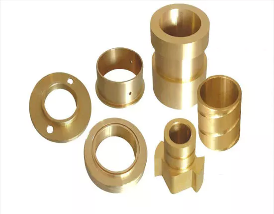
Tag Archives: tractor for

China high quality CE Approved Side Mower Tractor Mounted Verge Flail Mower Tow Behind Grass Cutter Flail Mower for Sale with Hot selling

Product Description

Side Flail Mower


Main Specifications:

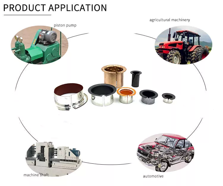
1. Used for the flat land grass, the weeds in the slope and bush side trimming.

2. Full dynamic balance testing before packing, to ensure the blades stability in high speed running and less noise.

3. Double Y shape blades, high cutting efficiency.

4. Bearing installed in 2 ends of roller, to make sure the flexibility of rotating and prevents hard abrasion.

5. Options for blade: (1) Y shape blade (2) Hammer 

6. It can be turned in sideways. Vertical and horizontal sides.

7. With belt tension pulley device.

8. With Hydraulic system, mainly for 20-30HP tractor

Model

EFDL-105 EFD-115 EFD-125
Dimension(mm) 1265×1355×836 12365*1355*835 1465*1355*836
Weight(Kg) 210Kg 225KG 240Kg
Cutting Width 1050mm 1150mm 1250mm
 PTO Input Speed 540r/min 540r/min 540r/min
Y shape blades 72 78 84
Power Required 20-25HP 20-30HP 20-30HP
3 point linkage  Cat.1  Cat.1 Cat.1
Packing size(mm) 1250×750×550 1350*750*550 1450×750×550

Customer Case


Company Profile

HangZhou CZPT Industry & Trade Co., Ltd., is a professional manufacturer and exporter of whole set of agriculture machines and garden tools. Our company was established since 2003 with Hanma Industry Company.

Our main products include rotovator, flail mower, finishing mower, CZPT mower, wood chipper, plow, cultivator, potato harvester/ planter and Japanese tractor parts, etc. Due to our super International quality standard and rapid & excellent after-sales service, CZPT machines are greatly popular in various markets around the world, and already reached to Europe, North America, South America, Australia, almost covers 80 countries in World.

LEFA always believe that we will take better farming life to you by top-quality laser cutting machine & CNC bending machine & professional paint-spraying & strong welding.

PROFESSIONAL PRODUCTION:

1.Professional team with rich experience

2.Powerful factory strength with CE certification

3.Best after-sales service

Packing & Shipping

Packaging Detail: Iron pallet or wooden cases
Delivery Detail: By sea or By air

1. Waterproof packing with the international export standard by 20ft, 40ftcontainer.
Wooden Case or Iron Pallet.
2. The whole set of machines size are large as normal, so we will use Waterproof materials to pack
all of them. The motor, gear box or other easily damaged parts, we will put them into box. 

We have a professional shipping department, they will try their best to save your container quantity.

Machine videos in YOUTOBE

          EFDL SIDE MOWERS

         EFGL SIDE MOWERS

          FM FINISHING MOWERS

        TM CZPT MOWERS

            RT ROTARY TILLERS

https://youtu.be/d3H1-yXUImc                                 AP-90 POTATO HARVESTER

https://youtu.be/AAkgnV_bY80                        LF-PT32 POTATO PLANTER

https://youtu.be/66geQQOUTLY                        wood chipper BX-42

https://youtu.be/iIVOwCTCl_c                       HAY BALER

FAQ:
Q1. How to buy 3 point rotary tiller?
Inquiry ———> Quotation ——–>Price reasonable ——->Check with specification —–>Proforma Invoice sent ————>Payment made ——-> Producing the items ——->Product shipment ———–> Customer confirm

Q2.How long is the delivery date for agriculture machinery cultivator?
A:In general, we can ship the goods within 30-45 days after receiving your payment. Of course, it also depends on your quantity.

Q3. How can I get to your factory to buy tractor cultivator?
A:We are located in HangZhou, only 1 hour’s distance to ZheJiang or HangZhou. You can fly to ZheJiang /HangZhou/HangZhou Airport , the transportation is very convenient

Q4.Do you have stock for rotary tiller?
A:In general, we have some stock, while if you need a bulk order, we still need time to produce it. Of course, we will inform all details you before your payment.

Q5: What’s your main products?
A: Our products are covered almost all farm machines and Japanese tractors parts, we can meet your any demands.

Q6. What is your terms of payment?
A: T/T, L/C, Paypal, Western Union
 

When your axle needs to be replaced

If you’re wondering when your axle needs to be replaced, you should be aware of these signs first. A damaged axle is usually a sign that your car is out of balance. To tell if the axle needs to be replaced, listen for the strange noise the wheels make as they move. A rhythmic popping sound when you hit bumps or turns indicates that your axle needs to be replaced. If this sounds familiar, you should visit a mechanic.
Driveshaft

Symptoms of a broken shaft

You may notice a clicking or clanking sound from the rear of the vehicle. The vibrations you feel while driving may also indicate damaged axles. In severe cases, your car may lose control, resulting in a crash. If you experience these symptoms, it’s time to visit your auto repair shop. For just a few hundred dollars, you can get your car back on the road, and you don’t have to worry about driving.
Often, damaged axles can be caused by a variety of causes, including poor shock or load bearing bearings. Other causes of axle problems can be an overloaded vehicle, potholes, or a car accident. A bad axle can also cause vibrations and power transmission failures while driving. A damaged axle can also be the result of hitting a curb or pothole. When shaft damage is the cause of these symptoms, it must be repaired immediately.
If your car’s front axle is bent, you may need to replace them at the same time. In this case, you need to remove all tires from the car, separate the driveshaft from the transmission, and remove the axle. Be sure to double check the alignment to make sure everything is ok. Your insurance may cover the cost of repairs, but you may need to pay a deductible before getting coverage.
Axle damage is a common cause of vehicle instability. Axles are key components of a car that transmit power from the engine to the wheels. If it breaks, your vehicle will not be able to drive without a working axle. Symptoms of damaged axles can include high-speed vibrations or crashes that can shake the entire car. When it breaks down, your vehicle won’t be able to carry the weight of your vehicle, so it’s important to get your car repaired as soon as possible.
When your axle is damaged, the wheels will not turn properly, causing the vehicle to crash. When your car has these problems, the brakes won’t work properly and can make your car unstable. The wheels also won’t line up properly, which can cause the brakes to fail. Also, a damaged axle can cause the brakes to become sluggish and sensitive. In addition to the obvious signs, you can also experience the sound of metal rubbing against metal.

Types of car axles

When you’re shopping for a new or used car, it’s important to know that there are different types of axles. Knowing the year, make, model, trim and body type will help you determine the type you need. For easy purchasing, you can also visit My Auto Shop and fill out the vehicle information checklist. You can also read about drivetrains and braking systems. After mastering the basic information of the vehicle, you can purchase the axle assembly.
There are 2 basic types of automotive axles: short axles and drive axles. The axle is the suspension system of the vehicle. They carry the drive torque of the engine and distribute the weight throughout the vehicle. While short shafts have the advantage of simpler maintenance, dead shafts are more difficult to repair. They’re also less flexible, which means they need to be durable enough to withstand harsh conditions.
Axles can be 1 of 3 basic types, depending on the weight and required force. Semi-floating shafts have a bearing in the sleeve. They attach to the wheel and spin to generate torque. Semi-pontoons are common in light pickup trucks and medium-duty vehicles. They are not as effective as floating axles, but still provide a solid foundation for wheel alignment. To keep the wheels aligned, these axles are an important part of the car.
The front axle is the largest of the 3 and can handle road shocks. It consists of 4 main parts: stub shaft, beam, universal pin and track rod. The front axle is also very important as it helps with steering and handling road shocks. The front axle should be strong and durable, as the front axle is most susceptible to road shocks.
Cars use 2 types of axles: live and dead. Live axles connect to the wheels and drive the vehicle. Dead axles do not drive the wheels and support the vehicle. Those with 2 wheels have live axles. Heavy trucks and trailers use 3 or more. The number of axles varies according to the weight and load of the vehicle. This will affect which type of axle you need.
Driveshaft

life expectancy

There are a few things to keep in mind when determining the life expectancy of an automotive axle. First, you should check for any signs of wear. A common sign is rust. If your vehicle is often driven in snow and ice, you may need to replace the axle. Also, you should listen for strange sounds from the wheels, such as rhythmic thumping.
Depending on the type of axle, your car may have an average lifespan of 70,000 miles. However, if you have an older car, the CV axles probably won’t last 5 years. In this case, you may wish to postpone the inspection. This way, you can save money on repairs. However, the next step is to replace the faulty CV shaft. This process can take anywhere from 1 hour to 3 hours.
Weaker axles will eventually break. If it were weakened, it would compromise the steering suspension, putting other road users at risk. Fortunately, proper maintenance will help extend the life of your axle. Here are some tips for extending its lifespan. A good rule of thumb is to never go over speed bumps. This will cause sudden breakage, possibly resulting in a car accident. To prolong the life of your vehicle’s axles, follow these tips.
Another thing to check is the CV connector. If loose, it can cause vibration or even breakage if not controlled. Loose axles can damage the body, suspension and differential. To make matters worse, the guard on the CV joint could tear prematurely, causing the shaft to come loose. Poor CV connections can damage the differential or transmission if left unchecked. So if you want to maximize the life expectancy of your car’s axles, consider getting them serviced as soon as possible.
Driveshaft

The cost of repairing a damaged axle

A damaged axle may need repair as it is responsible for transferring power from the engine to the wheels. A damaged axle can cause a crash or even loss of control. Repairing an axle is much simpler than dealing with an accident. However, damaged axles can cost hundreds of dollars or more. Therefore, it is important to know what to do if you suspect that your axle may have a damaged component.
When your car needs to be replaced or repaired, you should seek the help of a professional mechanic to keep your car safe. You can save a lot of money by contacting a local mechanic who will provide the parts and labor needed to repair the axle. Also, you can avoid accidents by fixing your car as soon as possible. While axles can be expensive, they can last for many years.
The cost of repairing a damaged axle depends on the amount of repairs required and the vehicle you are driving. Prices range from $300 to $1,000, depending on the car and its age. In most cases, it will cost you less than $200 if you know how to fix a damaged axle. For those without DIY auto repair experience, a new axle can cost as little as $500. A damaged axle is a dangerous part of driving.
Fortunately, there are several affordable ways to repair damaged axles. Choosing a mechanic who specializes in this type of repair is critical. They will assess the damage and decide whether to replace or repair the part. In addition to this, they will also road test your car after completing the repairs. If you are unsure about repair procedures or costs, call a mechanic.

China high quality CE Approved Side Mower Tractor Mounted Verge Flail Mower Tow Behind Grass Cutter Flail Mower for Sale     with Hot sellingChina high quality CE Approved Side Mower Tractor Mounted Verge Flail Mower Tow Behind Grass Cutter Flail Mower for Sale     with Hot selling

China Standard 3 Point Hitch Mounted Flail Mower for Tractor Mower with high quality

Product Description

Flail Mower

    1. Transmission: By sturdy toothed belts.
    2. Gearbox is made of gravity casting iron. Material performance is better. Not easy broken.
    3. With adjustable rear roller, the mowing height can be adjusted.
    4. The structure is firm and stable.
    5.  High welding processes
    6.  With front protection, it can prevent splashing.
    7. Y shape blades, hammer and vertical blades for grass. With double blades.
    8. Cat. I universal three-point hitch cardan shaft.


Model

EFD-95 EFD-105 EFD-115 EFD-125 EFD-135
Dimension(mm) 1040×700×520 1140×700×520 1240*700*520 1340×700×520 1440×700×520
Weight(Kg) 130 KG 145Kg 155KG 170Kg 175Kg
Cutting Width 950mm 1050mm 1150mm 1250mm 1350mm
 PTO Input Speed 540r/min 540r/min 540r/min 540r/min 540r/min
Y shape blades 60 72 78 84 84
Power Required 16-20HP 20-25HP 20-30HP 20-30HP 20-30HP
3 point linkage  Cat.1 Cat.1  Cat.1 Cat.1 Cat.1
Packing size(mm) 1150×750×550 1250×750×550 1350*750*550 1450×750×550 1550×750×550

Company Profile

HangZhou CZPT Industry & Trade Co., Ltd., is a professional manufacturer and exporter of whole set of agriculture machines and garden tools. Our company was established since 2003 with Hanma Industry Company.

Our main products include rotovator, flail mower, finishing mower, CZPT mower, wood chipper, plow, cultivator, potato harvester/ planter and Japanese tractor parts, etc. Due to our super International quality standard and rapid & excellent after-sales service, CZPT machines are greatly popular in various markets around the world, and already reached to Europe, North America, South America, Australia, almost covers 80 countries in World.

LEFA always believe that we will take better farming life to you by top-quality laser cutting machine & CNC bending machine & professional paint-spraying & strong welding.

PROFESSIONAL PRODUCTION:

1.Professional team with rich experience

2.Powerful factory strength with CE certification

3.Best after-sales service


Packing & Shipping

Packaging Detail: Iron pallet or wooden cases
Delivery Detail: By sea or By air

1. Waterproof packing with the international export standard by 20ft, 40ftcontainer.
Wooden Case or Iron Pallet.
2. The whole set of machines size are large as normal, so we will use Waterproof materials to pack
all of them. The motor, gear box or other easily damaged parts, we will put them into box. 

We have a professional shipping department, they will try their best to save your container quantity.

Machine videos in YOUTOBE

          EFDL SIDE MOWERS

         EFGL SIDE MOWERS

          FM FINISHING MOWERS

        TM CZPT MOWERS

            RT ROTARY TILLERS

https://youtu.be/d3H1-yXUImc                                 AP-90 POTATO HARVESTER

https://youtu.be/AAkgnV_bY80                        LF-PT32 POTATO PLANTER

https://youtu.be/66geQQOUTLY                        wood chipper BX-42

https://youtu.be/iIVOwCTCl_c                       HAY BALER

FAQ:
Q1. How to buy 3 point rotary tiller?
Inquiry ———> Quotation ——–>Price reasonable ——->Check with specification —–>Proforma Invoice sent ————>Payment made ——-> Producing the items ——->Product shipment ———–> Customer confirm

Q2.How long is the delivery date for agriculture machinery cultivator?
A:In general, we can ship the goods within 30-45 days after receiving your payment. Of course, it also depends on your quantity.

Q3. How can I get to your factory to buy tractor cultivator?
A:We are located in HangZhou, only 1 hour’s distance to ZheJiang or HangZhou. You can fly to ZheJiang /HangZhou/HangZhou Airport , the transportation is very convenient

Q4.Do you have stock for rotary tiller?
A:In general, we have some stock, while if you need a bulk order, we still need time to produce it. Of course, we will inform all details you before your payment.

Q5: What’s your main products?
A: Our products are covered almost all farm machines and Japanese tractors parts, we can meet your any demands.

Q6. What is your terms of payment?
A: T/T, L/C, Paypal, Western Union
 

How to Select a Worm Shaft and Gear For Your Project

You will learn about axial pitch PX and tooth parameters for a Worm Shaft 20 and Gear 22. Detailed information on these 2 components will help you select a suitable Worm Shaft. Read on to learn more….and get your hands on the most advanced gearbox ever created! Here are some tips for selecting a Worm Shaft and Gear for your project!…and a few things to keep in mind.
worm shaft

Gear 22

The tooth profile of Gear 22 on Worm Shaft 20 differs from that of a conventional gear. This is because the teeth of Gear 22 are concave, allowing for better interaction with the threads of the worm shaft 20. The worm’s lead angle causes the worm to self-lock, preventing reverse motion. However, this self-locking mechanism is not entirely dependable. Worm gears are used in numerous industrial applications, from elevators to fishing reels and automotive power steering.
The new gear is installed on a shaft that is secured in an oil seal. To install a new gear, you first need to remove the old gear. Next, you need to unscrew the 2 bolts that hold the gear onto the shaft. Next, you should remove the bearing carrier from the output shaft. Once the worm gear is removed, you need to unscrew the retaining ring. After that, install the bearing cones and the shaft spacer. Make sure that the shaft is tightened properly, but do not over-tighten the plug.
To prevent premature failures, use the right lubricant for the type of worm gear. A high viscosity oil is required for the sliding action of worm gears. In two-thirds of applications, lubricants were insufficient. If the worm is lightly loaded, a low-viscosity oil may be sufficient. Otherwise, a high-viscosity oil is necessary to keep the worm gears in good condition.
Another option is to vary the number of teeth around the gear 22 to reduce the output shaft’s speed. This can be done by setting a specific ratio (for example, 5 or 10 times the motor’s speed) and modifying the worm’s dedendum accordingly. This process will reduce the output shaft’s speed to the desired level. The worm’s dedendum should be adapted to the desired axial pitch.

Worm Shaft 20

When selecting a worm gear, consider the following things to consider. These are high-performance, low-noise gears. They are durable, low-temperature, and long-lasting. Worm gears are widely used in numerous industries and have numerous benefits. Listed below are just some of their benefits. Read on for more information. Worm gears can be difficult to maintain, but with proper maintenance, they can be very reliable.
The worm shaft is configured to be supported in a frame 24. The size of the frame 24 is determined by the center distance between the worm shaft 20 and the output shaft 16. The worm shaft and gear 22 may not come in contact or interfere with 1 another if they are not configured properly. For these reasons, proper assembly is essential. However, if the worm shaft 20 is not properly installed, the assembly will not function.
Another important consideration is the worm material. Some worm gears have brass wheels, which may cause corrosion in the worm. In addition, sulfur-phosphorous EP gear oil activates on the brass wheel. These materials can cause significant loss of load surface. Worm gears should be installed with high-quality lubricant to prevent these problems. There is also a need to choose a material that is high-viscosity and has low friction.
Speed reducers can include many different worm shafts, and each speed reducer will require different ratios. In this case, the speed reducer manufacturer can provide different worm shafts with different thread patterns. The different thread patterns will correspond to different gear ratios. Regardless of the gear ratio, each worm shaft is manufactured from a blank with the desired thread. It will not be difficult to find 1 that fits your needs.
worm shaft

Gear 22’s axial pitch PX

The axial pitch of a worm gear is calculated by using the nominal center distance and the Addendum Factor, a constant. The Center Distance is the distance from the center of the gear to the worm wheel. The worm wheel pitch is also called the worm pitch. Both the dimension and the pitch diameter are taken into consideration when calculating the axial pitch PX for a Gear 22.
The axial pitch, or lead angle, of a worm gear determines how effective it is. The higher the lead angle, the less efficient the gear. Lead angles are directly related to the worm gear’s load capacity. In particular, the angle of the lead is proportional to the length of the stress area on the worm wheel teeth. A worm gear’s load capacity is directly proportional to the amount of root bending stress introduced by cantilever action. A worm with a lead angle of g is almost identical to a helical gear with a helix angle of 90 deg.
In the present invention, an improved method of manufacturing worm shafts is described. The method entails determining the desired axial pitch PX for each reduction ratio and frame size. The axial pitch is established by a method of manufacturing a worm shaft that has a thread that corresponds to the desired gear ratio. A gear is a rotating assembly of parts that are made up of teeth and a worm.
In addition to the axial pitch, a worm gear’s shaft can also be made from different materials. The material used for the gear’s worms is an important consideration in its selection. Worm gears are usually made of steel, which is stronger and corrosion-resistant than other materials. They also require lubrication and may have ground teeth to reduce friction. In addition, worm gears are often quieter than other gears.

Gear 22’s tooth parameters

A study of Gear 22’s tooth parameters revealed that the worm shaft’s deflection depends on various factors. The parameters of the worm gear were varied to account for the worm gear size, pressure angle, and size factor. In addition, the number of worm threads was changed. These parameters are varied based on the ISO/TS 14521 reference gear. This study validates the developed numerical calculation model using experimental results from Lutz and FEM calculations of worm gear shafts.
Using the results from the Lutz test, we can obtain the deflection of the worm shaft using the calculation method of ISO/TS 14521 and DIN 3996. The calculation of the bending diameter of a worm shaft according to the formulas given in AGMA 6022 and DIN 3996 show a good correlation with test results. However, the calculation of the worm shaft using the root diameter of the worm uses a different parameter to calculate the equivalent bending diameter.
The bending stiffness of a worm shaft is calculated through a finite element model (FEM). Using a FEM simulation, the deflection of a worm shaft can be calculated from its toothing parameters. The deflection can be considered for a complete gearbox system as stiffness of the worm toothing is considered. And finally, based on this study, a correction factor is developed.
For an ideal worm gear, the number of thread starts is proportional to the size of the worm. The worm’s diameter and toothing factor are calculated from Equation 9, which is a formula for the worm gear’s root inertia. The distance between the main axes and the worm shaft is determined by Equation 14.
worm shaft

Gear 22’s deflection

To study the effect of toothing parameters on the deflection of a worm shaft, we used a finite element method. The parameters considered are tooth height, pressure angle, size factor, and number of worm threads. Each of these parameters has a different influence on worm shaft bending. Table 1 shows the parameter variations for a reference gear (Gear 22) and a different toothing model. The worm gear size and number of threads determine the deflection of the worm shaft.
The calculation method of ISO/TS 14521 is based on the boundary conditions of the Lutz test setup. This method calculates the deflection of the worm shaft using the finite element method. The experimentally measured shafts were compared to the simulation results. The test results and the correction factor were compared to verify that the calculated deflection is comparable to the measured deflection.
The FEM analysis indicates the effect of tooth parameters on worm shaft bending. Gear 22’s deflection on Worm Shaft can be explained by the ratio of tooth force to mass. The ratio of worm tooth force to mass determines the torque. The ratio between the 2 parameters is the rotational speed. The ratio of worm gear tooth forces to worm shaft mass determines the deflection of worm gears. The deflection of a worm gear has an impact on worm shaft bending capacity, efficiency, and NVH. The continuous development of power density has been achieved through advancements in bronze materials, lubricants, and manufacturing quality.
The main axes of moment of inertia are indicated with the letters A-N. The three-dimensional graphs are identical for the seven-threaded and one-threaded worms. The diagrams also show the axial profiles of each gear. In addition, the main axes of moment of inertia are indicated by a white cross.

China Standard 3 Point Hitch Mounted Flail Mower for Tractor Mower     with high qualityChina Standard 3 Point Hitch Mounted Flail Mower for Tractor Mower     with high quality

China high quality Dp High-End Mulcher Flail Mower for Sale Pto Drive for Tractor wholesaler

Product Description

Model DP/DPS-185 DP/DPS-195 DP/DPS-205
Structure Weight 425kg 439kg 450kg
Working Width 1820mm 1920mm 2571mm
PTO Turning Speed 540r/min 540r/min 540r/min
Flail Type 800g Hammer 800g Hammer 800g Hammer
Number Of Flails Hammer:32 Hammer:32 Hammer:32
Tractor HP 50-80hp 50-80hp 50-80hp
Machine Size 1980*850*850mm 2080*850*820mm 2180*850*820

Our description :DP Mower is with hydraulic system
DPS is without hydraulic system
Dimension of roller:∅108*10
Dimension of rotor:∅140*5

our advantage:A  whole complete set of production equipment lead to  short  lead time and better prices of machine.

Guarantee 1 year warranty of all our products.

Produce machines according to any requirements from our customers.

New machines will be developed  every year.

Every model of our machine will be tested before the delivery to the port.

If you want to visit our factory, our boss will give you a best reception.
 

Types of Pulley Systems

If you’ve ever tried to lift a pail of water, you’ve probably seen the pulley system in action. Pulleys are extremely useful tools for everything from household appliances to heavy industrial machinery. Different kinds of pulley systems are classified according to their amount of motion. Some types have fixed axes, while others have movable axes. Some common uses of pulleys are listed below.

two-wheel pulley

Pulleys are complex structures with thin-walled and thick-walled sections. Therefore, they require specific forging designs. The tool concept for the production of pulleys is shown in Figure 11.6. Using the generated tool, the pulley can be forged into different shapes. Process parameters must be optimized based on material, surface quality and metallographic analysis.
Pulleys are wheels mounted on shafts. Its main function is to assist the movement of heavy objects. A single-wheel pulley can change the direction of the force, enabling a person to pull heavy objects. A dual-wheel pulley distributes the weight evenly across both wheels, allowing it to lift the same weight with half the effort.
The mechanical advantage of a two-wheel pulley is that it reduces the force required by about half. A 100 kg object can be lifted with a force of 500 Newtons. The mechanical advantage of a pulley with 2 wheels is twice that of a single-wheel pulley. However, care should always be taken when using two-wheel pulleys.
Two-wheel pulleys can be fixed or movable. A single wheel pulley can only change direction when the load is placed on 1 side of the wheel. Two-wheel pulleys change direction when lifting a load, requiring half the force. Live wheels are better for heavier loads. The movable pulley can be adjusted with the load, and the load distribution is more uniform. Active pulleys can be used with single-rope or two-wheel pulleys.
A pulley system with 2 wheels is called a compound pulley. This type of pulley system has a complex design that reduces the force required to move the load. Two-wheel pulleys are common in industrial and construction environments. These pulleys require a lot of space to install and operate. Additionally, they require regular maintenance to avoid wear and tear.
pulley

composite pulley

Compound pulleys are used to increase lift. One fixed pulley is attached to the overhead while the other fixed pulley is attached to the load. This setup minimizes the force required to lift weights, allowing you to lift heavier weights. There are several different types of compound pulleys, each with their own strengths and weaknesses. Below are some examples of their application. Some of the most common are listed below.
Composite pulleys are usually made from 2 different types of wheels. The first 1 is fixed and secure. The second type, movable, is attached to something that moves. The third type, compound pulley, is a combination of a movable pulley and a fixed pulley. Below are 3 types of comparisons. The table below compares them and explains their advantages and disadvantages. Composite pulleys are the most versatile of the three.
The number of sheave segments that make up the composite sheave system increases the mechanical advantage of the system. Each segment adds 1 percent of the total weight, and the ideal mechanical advantage is 2 or more. So a compound pulley with 4 segments will lift three-quarters of the weight. This is because the force applied to the load is multiplied by four. The result is a better boost.
While composite pulleys have many uses, they are most commonly used on larger sailboats. These pulleys work by changing the direction of the control wire or by changing the mechanical force of the rope. They also make it easier to lift heavier objects. Composite pulleys are more expensive than simple pulleys, so consider your needs before buying. The advantages of composite pulleys outweigh the disadvantages.
A basic compound pulley is a device consisting of 2 wheels with fixed points. Ropes are looped around the wheels and are used to lift heavy objects. When you pull on the rope, the rope pulls the 2 wheels closer together. Serious injury could result if this equipment is installed incorrectly. Never exceed the lifting capacity of pulleys and other safety devices that may be attached. When using pulleys, be sure to follow the instructions on the mounting hardware to avoid accidents.
pulley

Fixed pulley

Moving pulleys and fixed pulleys are different types of mechanical devices. The movable pulley moves with the object it is used to lift. Because it attaches to the object it is used to lift, it is great for lifting heavy objects. These devices are used in construction cranes and multipurpose elevators. There are many different types of pulleys, and their uses vary widely. Below is a brief overview of these devices.
The simplest pulley set consists of a wheel that is mounted on the ceiling. A rope is attached at 1 end and a person pulls at the other end. The rope is strong enough to keep a person standing while lifting weights. It takes about 200 Newtons of force to lift a 20 kg weight. In contrast, a movable pulley requires a force of 1000N, which makes it easier to lift heavy objects.
Fixed pulleys are another common lifting device. They work by using ropes and slotted wheels attached to the object to be lifted. These devices are convenient to use because they are easy to set up. Moving the scroll wheel doesn’t change direction, so it’s easier to move objects without putting too much pressure on the back. Unlike a moving rope, a moving object will feel much lighter than its actual weight.
Fixed pulleys are widely used in construction and agriculture. Fixed pulleys can help lift supplies and equipment from scaffolding. These items are often heavy and difficult to lift directly. Fixed pulleys at the top of the scaffolding will allow people at the bottom to lift objects more easily. As a result, those at the bottom are less stressed and more productive. Fixed pulleys will save time and money compared to moving ropes.
Composite pulleys combine fixed and movable pulleys to increase the power of movement. A compound pulley system uses both types of pulleys and enables a person to change direction by reversing the direction of a force. The compound pulley system will save time and effort as the user only has to put in half the effort. Unlike moving ropes, composite pulleys are easy to adjust and are the most versatile system on the market.
pulley

Blocks and tackles

A pulley block system is a rope hoist that uses a set of pulleys mounted on a frame. The blocks are arranged in a row, and the threaded rope is called a pulley. Pulley systems help amplify the tension of the rope and are common in sailboats, cranes and drilling rigs. However, these systems are not without drawbacks.
The pulley pulley system can be equipped with as many pulleys as required. This method allows a person to lift heavy objects. The pulley block system can contain the required number of pulleys to achieve the desired height. The main disadvantage of pulley systems is that they create a lot of friction on the pulley shaft.
Pulley systems use 2 types of pulleys. A movable pulley is attached to the load, allowing it to move with the load. On the other hand, fixed pulleys are fixed on fixed points. Therefore, a pulley block system may consist of multiple pulleys mounted on a shaft. For example, the 2 pulleys attached to the shaft each have their own mechanical advantages.
Several types of tackle systems have been developed in recent centuries. The most basic is the gun mount, which uses 2 pulleys to lift the load. The mechanical advantage of such a system is 2 to 3 times the distance required by the rope to move the load. Depending on how they’re assembled, the system can lift 400 pounds with 80 or 100 pounds of force.
Another type of pulley is a combination of multiple wheels. The wheels on pulleys are supported by a housing or frame. The chain is attached to the pulley, and the rope is pulled to lift it. A combined pulley system will have multiple wheels. As the load increases, the force on the pulley also increases. This approach is generally more expensive than intercept and intercept systems.

China high quality Dp High-End Mulcher Flail Mower for Sale Pto Drive for Tractor     wholesaler China high quality Dp High-End Mulcher Flail Mower for Sale Pto Drive for Tractor     wholesaler

China Good quality Agricultural Verge Flail Mower with Rear Bonnet Pto Drive for Tractor wholesaler

Product Description


our description :Standard to medium duty flail mowers ideal for all grass cutting, particularly tall heavy grasses, heavy weeds and light brush. The perfect fit for your compact or utility tractor and ideal for orchard, nursery, vineyard, or gardening.

These cat. 1 / cat. 2 3 point hitch mounted flail mowers are made of high quality steel and will blaze through overgrown areas, storm debris, or sticks and small branches around your acreage, farm or hobby farm. These Terrain flail mowers meet the demanding needs of our Canadian land owners and will cut up to 1″ thick material.

With its fast blade tip speed and interchangeable blades it is perfect for your grounds keeping tasks. If you need to maintain more dense areas, the hammer blades will be CZPT to cut and mulch wooded material up to 1.5 inches in diameter. This model is great for acreages larger than 15 acres. Flail Mowers are useful for jobs where you are cutting grass on uneven ground, high grass, weeds, brush, and small saplings. A flail mower doesn’t throw grass, instead it cuts finely and leaves the cuttings on the ground where it was cut making it an excellent choice for those places where you could cause damage by throwing debris. Highway mowing and park maintenance often use flail mowers because they are less likely to throw objects during cutting.

The Z option gives you the opening rear access door for improved blade and rotor accessibility and can be opened in extreme conditions during operation to allow grass clippings and debris to escape, reducing build up. Use extreme caution.

our advantage:A  whole complete set of production equipment lead to  short  lead time and better prices of machine.

Guarantee 1 year warranty of all our products.

Produce machines according to any requirements from our customers.

New machines will be developed  every year.

Every model of our machine will be tested before the delivery to the port.

If you want to visit our factory, our boss will give you a best reception.
 

Screw Shaft Features Explained

When choosing the screw shaft for your application, you should consider the features of the screws: threads, lead, pitch, helix angle, and more. You may be wondering what these features mean and how they affect the screw’s performance. This article explains the differences between these factors. The following are the features that affect the performance of screws and their properties. You can use these to make an informed decision and purchase the right screw. You can learn more about these features by reading the following articles.

Threads

The major diameter of a screw thread is the larger of the 2 extreme diameters. The major diameter of a screw is also known as the outside diameter. This dimension can’t be directly measured, but can be determined by measuring the distance between adjacent sides of the thread. In addition, the mean area of a screw thread is known as the pitch. The diameter of the thread and pitch line are directly proportional to the overall size of the screw.
The threads are classified by the diameter and pitch. The major diameter of a screw shaft has the largest number of threads; the smaller diameter is called the minor diameter. The thread angle, also known as the helix angle, is measured perpendicular to the axis of the screw. The major diameter is the largest part of the screw; the minor diameter is the lower end of the screw. The thread angle is the half distance between the major and minor diameters. The minor diameter is the outer surface of the screw, while the top surface corresponds to the major diameter.
The pitch is measured at the crest of a thread. In other words, a 16-pitch thread has a diameter of 1 sixteenth of the screw shaft’s diameter. The actual diameter is 0.03125 inches. Moreover, a large number of manufacturers use this measurement to determine the thread pitch. The pitch diameter is a critical factor in successful mating of male and female threads. So, when determining the pitch diameter, you need to check the thread pitch plate of a screw.
screwshaft

Lead

In screw shaft applications, a solid, corrosion-resistant material is an important requirement. Lead screws are a robust choice, which ensure shaft direction accuracy. This material is widely used in lathes and measuring instruments. They have black oxide coatings and are suited for environments where rusting is not acceptable. These screws are also relatively inexpensive. Here are some advantages of lead screws. They are highly durable, cost-effective, and offer high reliability.
A lead screw system may have multiple starts, or threads that run parallel to each other. The lead is the distance the nut travels along the shaft during a single revolution. The smaller the lead, the tighter the thread. The lead can also be expressed as the pitch, which is the distance between adjacent thread crests or troughs. A lead screw has a smaller pitch than a nut, and the smaller the lead, the greater its linear speed.
When choosing lead screws, the critical speed is the maximum number of revolutions per minute. This is determined by the minor diameter of the shaft and its length. The critical speed should never be exceeded or the lead will become distorted or cracked. The recommended operational speed is around 80 percent of the evaluated critical speed. Moreover, the lead screw must be properly aligned to avoid excessive vibrations. In addition, the screw pitch must be within the design tolerance of the shaft.

Pitch

The pitch of a screw shaft can be viewed as the distance between the crest of a thread and the surface where the threads meet. In mathematics, the pitch is equivalent to the length of 1 wavelength. The pitch of a screw shaft also relates to the diameter of the threads. In the following, the pitch of a screw is explained. It is important to note that the pitch of a screw is not a metric measurement. In the following, we will define the 2 terms and discuss how they relate to 1 another.
A screw’s pitch is not the same in all countries. The United Kingdom, Canada, and the United States have standardized screw threads according to the UN system. Therefore, there is a need to specify the pitch of a screw shaft when a screw is being manufactured. The standardization of pitch and diameter has also reduced the cost of screw manufacturing. Nevertheless, screw threads are still expensive. The United Kingdom, Canada, and the United States have introduced a system for the calculation of screw pitch.
The pitch of a lead screw is the same as that of a lead screw. The diameter is 0.25 inches and the circumference is 0.79 inches. When calculating the mechanical advantage of a screw, divide the diameter by its pitch. The larger the pitch, the more threads the screw has, increasing its critical speed and stiffness. The pitch of a screw shaft is also proportional to the number of starts in the shaft.

Helix angle

The helix angle of a screw shaft is the angle formed between the circumference of the cylinder and its helix. Both of these angles must be equal to 90 degrees. The larger the lead angle, the smaller the helix angle. Some reference materials refer to angle B as the helix angle. However, the actual angle is derived from calculating the screw geometry. Read on for more information. Listed below are some of the differences between helix angles and lead angles.
High helix screws have a long lead. This length reduces the number of effective turns of the screw. Because of this, fine pitch screws are usually used for small movements. A typical example is a 16-mm x 5-inch screw. Another example of a fine pitch screw is a 12x2mm screw. It is used for small moves. This type of screw has a lower lead angle than a high-helix screw.
A screw’s helix angle refers to the relative angle of the flight of the helix to the plane of the screw axis. While screw helix angles are not often altered from the standard square pitch, they can have an effect on processing. Changing the helix angle is more common in two-stage screws, special mixing screws, and metering screws. When a screw is designed for this function, it should be able to handle the materials it is made of.
screwshaft

Size

The diameter of a screw is its diameter, measured from the head to the shaft. Screw diameters are standardized by the American Society of Mechanical Engineers. The diameters of screws range from 3/50 inches to 16 inches, and more recently, fractions of an inch have been added. However, shaft diameters may vary depending on the job, so it is important to know the right size for the job. The size chart below shows the common sizes for screws.
Screws are generally referred to by their gauge, which is the major diameter. Screws with a major diameter less than a quarter of an inch are usually labeled as #0 to #14 and larger screws are labeled as sizes in fractions of an inch. There are also decimal equivalents of each screw size. These measurements will help you choose the correct size for your project. The screws with the smaller diameters were not tested.
In the previous section, we described the different shaft sizes and their specifications. These screw sizes are usually indicated by fractions of an inch, followed by a number of threads per inch. For example, a ten-inch screw has a shaft size of 2” with a thread pitch of 1/4″, and it has a diameter of 2 inches. This screw is welded to a two-inch Sch. 40 pipe. Alternatively, it can be welded to a 9-inch O.A.L. pipe.
screwshaft

Shape

Screws come in a wide variety of sizes and shapes, from the size of a quarter to the diameter of a U.S. quarter. Screws’ main function is to hold objects together and to translate torque into linear force. The shape of a screw shaft, if it is round, is the primary characteristic used to define its use. The following chart shows how the screw shaft differs from a quarter:
The shape of a screw shaft is determined by 2 features: its major diameter, or distance from the outer edge of the thread on 1 side to the inner smooth surface of the shaft. These are generally 2 to 16 millimeters in diameter. Screw shafts can have either a fully threaded shank or a half-threaded shank, with the latter providing better stability. Regardless of whether the screw shaft is round or domed, it is important to understand the different characteristics of a screw before attempting to install it into a project.
The screw shaft’s diameter is also important to its application. The ball circle diameter refers to the distance between the center of 2 opposite balls in contact with the grooves. The root diameter, on the other hand, refers to the distance between the bottommost grooves of the screw shaft. These are the 2 main measurements that define the screw’s overall size. Pitch and nominal diameter are important measurements for a screw’s performance in a particular application.

Lubrication

In most cases, lubrication of a screw shaft is accomplished with grease. Grease is made up of mineral or synthetic oil, thickening agent, and additives. The thickening agent can be a variety of different substances, including lithium, bentonite, aluminum, and barium complexes. A common classification for lubricating grease is NLGI Grade. While this may not be necessary when specifying the type of grease to use for a particular application, it is a useful qualitative measure.
When selecting a lubricant for a screw shaft, the operating temperature and the speed of the shaft determine the type of oil to use. Too much oil can result in heat buildup, while too little can lead to excessive wear and friction. The proper lubrication of a screw shaft directly affects the temperature rise of a ball screw, and the life of the assembly. To ensure the proper lubrication, follow the guidelines below.
Ideally, a low lubrication level is appropriate for medium-sized feed stuff factories. High lubrication level is appropriate for larger feed stuff factories. However, in low-speed applications, the lubrication level should be sufficiently high to ensure that the screws run freely. This is the only way to reduce friction and ensure the longest life possible. Lubrication of screw shafts is an important consideration for any screw.

China Good quality Agricultural Verge Flail Mower with Rear Bonnet Pto Drive for Tractor     wholesaler China Good quality Agricultural Verge Flail Mower with Rear Bonnet Pto Drive for Tractor     wholesaler

China high quality Farm 20-25HP 3 Point Hitch Mini Tractor Flail Mower Pto Drive Mower for Sale with Great quality

Product Description

MODEL EF85 EF95 EF105 EF115 EF125
Structure Weight 133kg 145kg 151kg 158kg 165kg
Working Width 829mm 929mm 1571mm 1129mm 1229mm
PTO Turning Speed 540r/min 540r/min 540r/min 540r/min 540r/min
Flail Type Hammer/Y Blade
Number of Flail Hammer 12 /Y Blade 24 Hammer 18 /Y Blade 36 Hammer 18 /Y Blade 36 Hammer 18 /Y Blade 36 Hammer 18 /Y Blade 36
Tractor HP 14-18hp 16-20hp 20-30hp 20-30hp 25-35hp


MODEL EF135 EF145 EF155 EF165 EF175
Structure Weight 175kg 178kg 182kg 190kg 198kg
Working Width 1329mm 1429mm 1529mm 1629mm 1729mm
PTO Turning Speed 540r/min 540r/min 540r/min 540r/min 540r/min
Flail Type Y Blade/Hammer
Number of Flail Hammer 24 /Y Blade48 Hammer 24 /Y Blade48 Hammer 24 /Y Blade48 Hammer 24 /Y Blade48 Hammer 30 /Y Blade 60
Tractor HP 25-35hp 25-35hp 30-40hp 30-40hp 30-40hp

Perfect for use after storms when debris is scattered throughout areas usually maintained with normal mowers~ Multi-purpose machines for mulching sticks~ Ideal for thick grass, sticks, undergrowth and light vine mulching~ Vegetable & pasture topping~ Roadside maintenance.

HangZhou Qianyi Machinery Technology Co.,Ltd existing staff 50 people, in 2571 passed the ISO9001 quality system certification and passed CE certification.

Accumulated after years of development, we have many advanced equipment, like Germany fast Trulaser3030 laser cutting ,machine, CNC punch press TruPunch1000, CNC shearing machine, CNC lathe, bending machine, seam welding machine and more than 1 formula 1-160-1 high-end mechanical production equipment.

We provide good design, to help customers reduce costs of development and improve production efficiency. With complete testing equipment, strict quality control and abundant technical force, our machines are mainly exported to European, North American and Southeast Asian countries.

All of our machines are with 1 year warranty. We often insist on 1 principle”Better quality!Better service!Better price!”

What is the purpose of the bushing?

If you notice the truck making noises when cornering, the bushings may be worn. You may need to replace the ball joint or stabilizer bar, but a simple inspection will reveal that the noise is coming from the bushing. The noise from a worn bushing on a metal joint can mimic the sound of other problems in the suspension, such as a loose stabilizer bar or a failed ball joint.
bushing

Function

What is the purpose of the bushing? They play an important role in the operation of various mechanical parts. Their main functions include reducing the clearance between the shaft and the bearing and reducing the leakage of the valve. Bushings are used in different ways to ensure smooth operation and longevity. However, some new designers don’t appreciate the functionality of the case. So let’s discuss these features. Some of their most common applications are listed below.
First, the shell does a lot of things. They reduce noise, control vibration, and provide amazing protection for all kinds of industrial equipment. Large industrial equipment faces more wear, vibration and noise, which can render it completely inoperable. Bushings help prevent this by reducing noise and vibration. Bushing sets also extend equipment life and improve its performance. Therefore, you should not underestimate the importance of the casing in your device.
Another common function of bushings is to support components during assembly. In other words, the bushing reduces the risk of machine wear. In addition to this, they are superior to bearings, which are notoriously expensive to maintain. However, they are still useful, and their versatility cannot be overemphasized. If you’re considering installing one, you’ll be glad you did! These products have become a necessity in the modern industrial world. If you’re wondering how to choose one, here are some of the most common bushing uses.
Electrical bushings are an important part of many electrical equipment. They carry high voltage currents through the enclosure and provide an insulating barrier between live conductors and metal bodies at ground potential. They are made of a central conductive rod (usually copper or aluminum) and surrounding insulators made of composite resin silicone rubber. Additionally, the bushings are made of various materials. Whether copper, aluminum or plastic, they are an important part of many types of electrical equipment.

type

There are several different types of bushings on the market today. They may be cheap but they are of good quality. These products can be used in telephones, cable television, computer data lines and alarm systems. The key to buying these products online is finding the right appliance store and choosing a high-quality product. An online appliance store should have comprehensive information and ease of use. For the right electrical bushing, you should look for reliable online stores with the best prices and high quality products.
Capacitive grading bushings use conductive foils inserted into paper to stabilize the electric field and balance the internal energy of the bushing. The conductive foil acts as a capacitive element, connecting the high voltage conductor to ground. These types of bushings are sometimes referred to as capacitor grade bushings. Capacitive grading bushings are usually made of paper impregnated with epoxy resin or mineral oil.
When buying enclosures, you should know how they are used. Unlike ball bearings, bushings should be stored upright so that they are in the correct working position. This is because horizontal placement can cause air bubbles to form in the fill insulation. It is also important to store the bushing properly to prevent damage. The wrong way to store these components can result in costly repairs.
In addition to the physical structure, the bushing insulation must also be effective over the long term. It must resist partial discharge and working electric field stress. The material and design of the bushing can vary widely. Early on, porcelain-based materials were popular in bushing designs. Porcelain was chosen because of its low cost of production and very low linear expansion. Ceramic bushings, on the other hand, require a lot of metal fittings and flexible seals.
bushing

Durability

The RIG 3 Bushing Durability Test Standard simulates real-world service conditions for automotive bushings. This three-channel test standard varies casing loads and stresses by applying a range of different load conditions and various control factors. This test is critical to the durability of the case, as it accurately reproduces the dynamic loads that occur during normal use. This test is a key component of the automotive industry and is widely used in many industries.
The Advanced Casing Model has 5 modules to address asymmetry, nonlinearity, and hysteresis. This model also represents the CZPT lag model. The model can be parameterized in the time domain using MATLAB, and the results can be exported to other simulation software. The developed bushing model is a key component in the durability and performance of vehicle suspension components.
A conductive material is coated on the inner surface of the sleeve. The coating is chosen to conduct a certain amount of current. The conductive path extends from the blade spacer 126 to the sleeve projecting edge 204 and then through the housing 62 to the ground. The coating is made of a low friction material and acts as a wear surface against the bushing sidewall 212 and the housing 62 .
Another important factor in a bushing’s durability is its ability to friction. The higher the operating speed, the greater the load on the bushing. Since bushings are designed for lighter loads and slower speeds, they cannot handle large loads at high speeds. The P-max or V-max value of a bushing is its maximum load or speed at 0 rpm. The PV value must be lower than the manufacturer’s PV value.

price

If you need to replace the bushing on the control arm, you should understand the cost involved. This repair can be expensive, depending on the make and model of your car. Generally, you should pay between $105 and $180 for a replacement. However, you can choose to have it done by a mechanic at a lower cost. The labor cost for this job can be around $160, depending on your automaker.
The cost of replacing the control arm bushings can range from $200 on the low end to $500 on a luxury car. While parts are cheap, labor costs are the highest. Mechanics had to remove suspension and wheel assemblies to replace bushings. If you have some mechanical knowledge, you can replace the bushing yourself. Control arm bushings on the wheel side are usually about $20 each. Still, if you’re not a mechanic, you can save money by doing it yourself.
bushing

Install

Press-fit bushings are installed using a retaining ring with a diameter 0.3/0.4 mm larger than the inner diameter of the bushing. To ensure accurate installation, use a mechanically driven, pneumatic or hydraulic drill and insert the bushing into the appropriate hole. This process is best done using mounting holes with drilled holes for the clamps. Make sure the mounting hole is in the center of the bushing and free of debris.
Once the bushing is positioned, use a vise to install its nut. A cold bushing will compress and fit the shell better. Place the sleeve in the refrigerator for at least 24 hours to aid installation. After removing the bushing from the refrigerator, make sure it has enough diameter to fit into the enclosure. Next, place the opposite socket into the enclosure and use it as a stand. After a few minutes, the bushing should be fully seated in the housing.
Install the new bushing into the housing hole. If the previous 1 had a metal case, insert the new 1 through the taper. Always lubricate the inner and outer surfaces of the bushing. Then, apply pressure to the inner metal sleeve of the new bushing. You may notice that the new bushing does not exactly match the housing hole. However, that’s okay because the outer diameter of the bushing is larger than the outer diameter of the hub drive.
The installation of the bushing requires the use of the hydraulic unit 16 . Hydraulic unit 16 is located near the #1 journal of the camshaft and extends from #2 to #7. Hydraulic fluid forces piston 22 away from the outer end of cylinder 20 and pushes shaft 14 forward. The shaft is then moved forward, pushing the bushing 17 onto the piston. Multiple bushings can be installed in a single engine.

China high quality Farm 20-25HP 3 Point Hitch Mini Tractor Flail Mower Pto Drive Mower for Sale     with Great qualityChina high quality Farm 20-25HP 3 Point Hitch Mini Tractor Flail Mower Pto Drive Mower for Sale     with Great quality

China best Garden Shredder Flail Mower Pto Drive for Tractor near me supplier

Product Description

MODEL EF85 EF95 EF105 EF115 EF125
Structure Weight 133kg 145kg 151kg 158kg 165kg
Working Width 829mm 929mm 1571mm 1129mm 1229mm
PTO Turning Speed 540r/min 540r/min 540r/min 540r/min 540r/min
Flail Type Hammer/Y Blade
Number of Flail Hammer 12 /Y Blade 24 Hammer 18 /Y Blade 36 Hammer 18 /Y Blade 36 Hammer 18 /Y Blade 36 Hammer 18 /Y Blade 36
Tractor HP 14-18hp 16-20hp 20-30hp 20-30hp 25-35hp


MODEL EF135 EF145 EF155 EF165 EF175
Structure Weight 175kg 178kg 182kg 190kg 198kg
Working Width 1329mm 1429mm 1529mm 1629mm 1729mm
PTO Turning Speed 540r/min 540r/min 540r/min 540r/min 540r/min
Flail Type Y Blade/Hammer
Number of Flail Hammer 24 /Y Blade48 Hammer 24 /Y Blade48 Hammer 24 /Y Blade48 Hammer 24 /Y Blade48 Hammer 30 /Y Blade 60
Tractor HP 25-35hp 25-35hp 30-40hp 30-40hp 30-40hp

Our description :Perfect for use after storms when debris is scattered throughout areas usually maintained with normal mowers~ Multi-purpose machines for mulching sticks~ Ideal for thick grass, sticks, undergrowth and light vine mulching~ Vegetable & pasture topping~ Roadside maintenance.

our advantage:A  whole complete set of production equipment lead to  short  lead time and better prices of machine.

Guarantee 1 year warranty of all our products.

Produce machines according to any requirements from our customers.

New machines will be developed  every year.

Every model of our machine will be tested before the delivery to the port.

If you want to visit our factory, our boss will give you a best reception.
 

Different parts of the drive shaft

The driveshaft is the flexible rod that transmits torque between the transmission and the differential. The term drive shaft may also refer to a cardan shaft, a transmission shaft or a propeller shaft. Parts of the drive shaft are varied and include:
The driveshaft is a flexible rod that transmits torque from the transmission to the differential

When the driveshaft in your car starts to fail, you should seek professional help as soon as possible to fix the problem. A damaged driveshaft can often be heard. This noise sounds like “tak tak” and is usually more pronounced during sharp turns. However, if you can’t hear the noise while driving, you can check the condition of the car yourself.
The drive shaft is an important part of the automobile transmission system. It transfers torque from the transmission to the differential, which then transfers it to the wheels. The system is complex, but still critical to the proper functioning of the car. It is the flexible rod that connects all other parts of the drivetrain. The driveshaft is the most important part of the drivetrain, and understanding its function will make it easier for you to properly maintain your car.
Driveshafts are used in different vehicles, including front-wheel drive, four-wheel drive, and front-engine rear-wheel drive. Drive shafts are also used in motorcycles, locomotives and ships. Common front-engine, rear-wheel drive vehicle configurations are shown below. The type of tube used depends on the size, speed and strength of the drive shaft.
The output shaft is also supported by the output link, which has 2 identical supports. The upper part of the drive module supports a large tapered roller bearing, while the opposite flange end is supported by a parallel roller bearing. This ensures that the torque transfer between the differentials is efficient. If you want to learn more about car differentials, read this article.
air-compressor

It is also known as cardan shaft, propeller shaft or drive shaft

A propshaft or propshaft is a mechanical component that transmits rotation or torque from an engine or transmission to the front or rear wheels of a vehicle. Because the axes are not directly connected to each other, it must allow relative motion. Because of its role in propelling the vehicle, it is important to understand the components of the driveshaft. Here are some common types.
Isokinetic Joint: This type of joint guarantees that the output speed is the same as the input speed. To achieve this, it must be mounted back-to-back on a plane that bisects the drive angle. Then mount the 2 gimbal joints back-to-back and adjust their relative positions so that the velocity changes at 1 joint are offset by the other joint.
Driveshaft: The driveshaft is the transverse shaft that transmits power to the front wheels. Driveshaft: The driveshaft connects the rear differential to the transmission. The shaft is part of a drive shaft assembly that includes a drive shaft, a slip joint, and a universal joint. This shaft provides rotational torque to the drive shaft.
Dual Cardan Joints: This type of driveshaft uses 2 cardan joints mounted back-to-back. The center yoke replaces the intermediate shaft. For the duplex universal joint to work properly, the angle between the input shaft and the output shaft must be equal. Once aligned, the 2 axes will operate as CV joints. An improved version of the dual gimbal is the Thompson coupling, which offers slightly more efficiency at the cost of added complexity.
air-compressor

It transmits torque at different angles between driveline components

A vehicle’s driveline consists of various components that transmit power from the engine to the wheels. This includes axles, propshafts, CV joints and differentials. Together, these components transmit torque at different angles between driveline components. A car’s powertrain can only function properly if all its components work in harmony. Without these components, power from the engine would stop at the transmission, which is not the case with a car.
The CV driveshaft design provides smoother operation at higher operating angles and extends differential and transfer case life. The assembly’s central pivot point intersects the joint angle and transmits smooth rotational power and surface speed through the drivetrain. In some cases, the C.V. “U” connector. Drive shafts are not the best choice because the joint angles of the “U” joints are often substantially unequal and can cause torsional vibration.
Driveshafts also have different names, including driveshafts. A car’s driveshaft transfers torque from the transmission to the differential, which is then distributed to other driveline components. A power take-off (PTO) shaft is similar to a prop shaft. They transmit mechanical power to connected components. They are critical to the performance of any car. If any of these components are damaged, the entire drivetrain will not function properly.
A car’s powertrain can be complex and difficult to maintain. Adding vibration to the drivetrain can cause premature wear and shorten overall life. This driveshaft tip focuses on driveshaft assembly, operation, and maintenance, and how to troubleshoot any problems that may arise. Adding proper solutions to pain points can extend the life of the driveshaft. If you’re in the market for a new or used car, be sure to read this article.

it consists of several parts

“It consists of several parts” is 1 of 7 small prints. This word consists of 10 letters and is 1 of the hardest words to say. However, it can be explained simply by comparing it to a cow’s kidney. The cocoa bean has several parts, and the inside of the cocoa bean before bursting has distinct lines. This article will discuss the different parts of the cocoa bean and provide a fun way to learn more about the word.
air-compressor

Replacement is expensive

Replacing a car’s driveshaft can be an expensive affair, and it’s not the only part that needs servicing. A damaged drive shaft can also cause other problems. This is why getting estimates from different repair shops is essential. Often, a simple repair is cheaper than replacing the entire unit. Listed below are some tips for saving money when replacing a driveshaft. Listed below are some of the costs associated with repairs:
First, learn how to determine if your vehicle needs a driveshaft replacement. Damaged driveshaft components can cause intermittent or lack of power. Additionally, improperly installed or assembled driveshaft components can cause problems with the daily operation of the car. Whenever you suspect that your car needs a driveshaft repair, seek professional advice. A professional mechanic will have the knowledge and experience needed to properly solve the problem.
Second, know which parts need servicing. Check the u-joint bushing. They should be free of crumbs and not cracked. Also, check the center support bearing. If this part is damaged, the entire drive shaft needs to be replaced. Finally, know which parts to replace. The maintenance cost of the drive shaft is significantly lower than the maintenance cost. Finally, determine if the repaired driveshaft is suitable for your vehicle.
If you suspect your driveshaft needs service, make an appointment with a repair shop as soon as possible. If you are experiencing vibration and rough riding, driveshaft repairs may be the best way to prevent costly repairs in the future. Also, if your car is experiencing unusual noise and vibration, a driveshaft repair may be a quick and easy solution. If you don’t know how to diagnose a problem with your car, you can take it to a mechanic for an appointment and a quote.

China best Garden Shredder Flail Mower Pto Drive for Tractor     near me supplier China best Garden Shredder Flail Mower Pto Drive for Tractor     near me supplier

China Standard Agricultural 3 Point Tractor Mounted Pto Drive Tractor Flail Mower for Sale near me shop

Product Description


MODEL EFG105 EFG115 EFG125 EFG135
Structure Weight 230kg 245kg 257kg 272kg
Working Width 1.02m 1.12m 1.22m 1.32m
PTO Turning Speed 540r/min 540r/min 540r/min 540r/min
Flail Type Y Blade/Hammer
Number of Flail Y Blade:36 / Hammer:18 Y Blade:36 / Hammer:18 Y Blade:36 / Hammer:18 Y Blade :44/ Hammer:22
Tractor HP 15-20hp 15-20hp 15-20hp 18-25hp


MODEL EFG145 EFG155 EFG165 EFG175
Structure Weight 287kg 302kg 317kg 329kg
Working Width 1.42m 1.52m 1.62m 1.72m
PTO Turning Speed 540r/min 540r/min 540r/min 540r/min
Flail Type Y Blade/Hammer
Number of Flail Y Blade :44/ Hammer:22 Y Blade:44 / Hammer:22 Y Blade:52/ Hammer:26 Y Blade :52/ Hammer:26
Tractor HP 20-30hp 20-30hp 25-35hp 30-35hp

The EFG Series Flail Mower belongs to Medium Duty. Ideal for an orchard, nursery, vineyard, in the greenhouse or for gardening. With good blades and interchangeable blades, it is ideal for your ground maintenance. By putting on the Grass Mulching Blades you can maintain the grass area around your home, plus cut and mulch small twigs. If you need to maintain more dense areas, install the Hammer Blades and you will be CZPT to cut and mulch wooded material up to 2 inches in diameter.

HangZhou Qianyi Machinery Technology Co.,Ltd existing staff 50 people, in 2571 passed the ISO9001 quality system certification and passed CE certification.

Accumulated after years of development, we have many advanced equipment, like Germany fast Trulaser3030 laser cutting ,machine, CNC punch press TruPunch1000, CNC shearing machine, CNC lathe, bending machine, seam welding machine and more than 1 formula 1-160-1 high-end mechanical production equipment.

We provide good design, to help customers reduce costs of development and improve production efficiency. With complete testing equipment, strict quality control and abundant technical force, our machines are mainly exported to European, North American and Southeast Asian countries.

All of our machines are with 1 year warranty. We often insist on 1 principle”Better quality!Better service!Better price!”

What Are the Advantages of a Splined Shaft?

If you are looking for the right splined shaft for your machine, you should know a few important things. First, what type of material should be used? Stainless steel is usually the most appropriate choice, because of its ability to offer low noise and fatigue failure. Secondly, it can be machined using a slotting or shaping machine. Lastly, it will ensure smooth motion. So, what are the advantages of a splined shaft?
Stainless steel is the best material for splined shafts

When choosing a splined shaft, you should consider its hardness, quality, and finish. Stainless steel has superior corrosion and wear resistance. Carbon steel is another good material for splined shafts. Carbon steel has a shallow carbon content (about 1.7%), which makes it more malleable and helps ensure smooth motion. But if you’re not willing to spend the money on stainless steel, consider other options.
There are 2 main types of splines: parallel splines and crowned splines. Involute splines have parallel grooves and allow linear and rotary motion. Helical splines have involute teeth and are oriented at an angle. This type allows for many teeth on the shaft and minimizes the stress concentration in the stationary joint.
Large evenly spaced splines are widely used in hydraulic systems, drivetrains, and machine tools. They are typically made from carbon steel (CR10) and stainless steel (AISI 304). This material is durable and meets the requirements of ISO 14-B, formerly DIN 5463-B. Splined shafts are typically made of stainless steel or C45 steel, though there are many other materials available.
Stainless steel is the best material for a splined shaft. This metal is also incredibly affordable. In most cases, stainless steel is the best choice for these shafts because it offers the best corrosion resistance. There are many different types of splined shafts, and each 1 is suited for a particular application. There are also many different types of stainless steel, so choose stainless steel if you want the best quality.
For those looking for high-quality splined shafts, CZPT Spline Shafts offer many benefits. They can reduce costs, improve positional accuracy, and reduce friction. With the CZPT TFE coating, splined shafts can reduce energy and heat buildup, and extend the life of your products. And, they’re easy to install – all you need to do is install them.
splineshaft

They provide low noise, low wear and fatigue failure

The splines in a splined shaft are composed of 2 main parts: the spline root fillet and the spline relief. The spline root fillet is the most critical part, because fatigue failure starts there and propagates to the relief. The spline relief is more susceptible to fatigue failure because of its involute tooth shape, which offers a lower stress to the shaft and has a smaller area of contact.
The fatigue life of splined shafts is determined by measuring the S-N curve. This is also known as the Wohler curve, and it is the relationship between stress amplitude and number of cycles. It depends on the material, geometry and way of loading. It can be obtained from a physical test on a uniform material specimen under a constant amplitude load. Approximations for low-alloy steel parts can be made using a lower-alloy steel material.
Splined shafts provide low noise, minimal wear and fatigue failure. However, some mechanical transmission elements need to be removed from the shaft during assembly and manufacturing processes. The shafts must still be capable of relative axial movement for functional purposes. As such, good spline joints are essential to high-quality torque transmission, minimal backlash, and low noise. The major failure modes of spline shafts include fretting corrosion, tooth breakage, and fatigue failure.
The outer disc carrier spline is susceptible to tensile stress and fatigue failure. High customer demands for low noise and low wear and fatigue failure makes splined shafts an excellent choice. A fractured spline gear coupling was received for analysis. It was installed near the top of a filter shaft and inserted into the gearbox motor. The service history was unknown. The fractured spline gear coupling had longitudinally cracked and arrested at the termination of the spline gear teeth. The spline gear teeth also exhibited wear and deformation.
A new spline coupling method detects fault propagation in hollow cylindrical splined shafts. A spline coupling is fabricated using an AE method with the spline section unrolled into a metal plate of the same thickness as the cylinder wall. In addition, the spline coupling is misaligned, which puts significant concentration on the spline teeth. This further accelerates the rate of fretting fatigue and wear.
A spline joint should be lubricated after 25 hours of operation. Frequent lubrication can increase maintenance costs and cause downtime. Moreover, the lubricant may retain abrasive particles at the interfaces. In some cases, lubricants can even cause misalignment, leading to premature failure. So, the lubrication of a spline coupling is vital in ensuring proper functioning of the shaft.
The design of a spline coupling can be optimized to enhance its wear resistance and reliability. Surface treatments, loads, and rotation affect the friction properties of a spline coupling. In addition, a finite element method was developed to predict wear of a floating spline coupling. This method is feasible and provides a reliable basis for predicting the wear and fatigue life of a spline coupling.
splineshaft

They can be machined using a slotting or shaping machine

Machines can be used to shape splined shafts in a variety of industries. They are useful in many applications, including gearboxes, braking systems, and axles. A slotted shaft can be manipulated in several ways, including hobbling, broaching, and slotting. In addition to shaping, splines are also useful in reducing bar diameter.
When using a slotting or shaping machine, the workpiece is held against a pedestal that has a uniform thickness. The machine is equipped with a stand column and limiting column (Figure 1), each positioned perpendicular to the upper surface of the pedestal. The limiting column axis is located on the same line as the stand column. During the slotting or shaping process, the tool is fed in and out until the desired space is achieved.
One process involves cutting splines into a shaft. Straddle milling, spline shaping, and spline cutting are 2 common processes used to create splined shafts. Straddle milling involves a fixed indexing fixture that holds the shaft steady, while rotating milling cutters cut the groove in the length of the shaft. Several passes are required to ensure uniformity throughout the spline.
Splines are a type of gear. The ridges or teeth on the drive shaft mesh with grooves in the mating piece. A splined shaft allows the transmission of torque to a mate piece while maximizing the power transfer. Splines are used in heavy vehicles, construction, agriculture, and massive earthmoving machinery. Splines are used in virtually every type of rotary motion, from axles to transmission systems. They also offer better fatigue life and reliability.
Slotting or shaping machines can also be used to shape splined shafts. Slotting machines are often used to machine splined shafts, because it is easier to make them with these machines. Using a slotting or shaping machine can result in splined shafts of different sizes. It is important to follow a set of spline standards to ensure your parts are manufactured to the highest standards.
A milling machine is another option for producing splined shafts. A spline shaft can be set up between 2 centers in an indexing fixture. Two side milling cutters are mounted on an arbor and a spacer and shims are inserted between them. The arbor and cutters are then mounted to a milling machine spindle. To make sure the cutters center themselves over the splined shaft, an adjustment must be made to the spindle of the machine.
The machining process is very different for internal and external splines. External splines can be broached, shaped, milled, or hobbed, while internal splines cannot. These machines use hard alloy, but they are not as good for internal splines. A machine with a slotting mechanism is necessary for these operations.

China Standard Agricultural 3 Point Tractor Mounted Pto Drive Tractor Flail Mower for Sale     near me shop China Standard Agricultural 3 Point Tractor Mounted Pto Drive Tractor Flail Mower for Sale     near me shop

China OEM Medium Size Verge Flail Mower Pto Drive for Tractor with CE Certification with Good quality

Product Description


MODEL QYM110 QYM130 QYM150
Structure Weight 240KG 280KG 320KG
Working Width 1050 1250 1450
Flail Type Hammer Hammer Hammer
NO. Of Flail 18 22 26
Tractor HP 20HP-30HP 20HP-30HP 30HP-50HP
Side Shift Type Mechanical/Hydraulic Mechanical/Hydraulic Mechanical/Hydraulic

our description QYM flail mowers are designed to be centrally mounted. Each machine features double skin construction so that rocks and debris will not damage the outer hull. Mowing height is controlled with an adjustable rear roller, and side skids help protect the machine end flanges from wear.
Equipped with heavy hammer blades, the machine will cut brush material up to 1-¾”, and leave a smooth finish on grass as well. Optional Y-flails can be used if cutting grass is the main application.

our advantage:A  whole complete set of production equipment lead to  short  lead time and better prices of machine.

Guarantee 1 year warranty of all our products.

Produce machines according to any requirements from our customers.

New machines will be developed  every year.

Every model of our machine will be tested before the delivery to the port.

If you want to visit our factory, our boss will give you a best reception.
 

The benefits of using pulleys

A pulley is a mechanical device that converts force into rotation. There are many advantages to using pulleys. Let’s take a look at a few of them. This article will describe the advantages, types, applications, and power sources of pulleys. You can then choose the pulley that best suits your specific needs. If you’re looking for a new tool to help you with a certain task, this article is for you.
pulley

Mechanical advantage

The mechanical advantage of a pulley can be defined as the ratio of applied force to the applied force. The mechanical advantage of a pulley can be calculated by considering several factors, including weight and friction. It can be calculated by the force applied per unit length of rope and the number of pulleys used. In a single-circuit system, the force required to lift a heavy object is equal to the user’s body weight.
The mechanical advantage of a pulley can be realized by comparing it to a seesaw. Both uses of rope are suitable for lifting objects. A rope 4 times heavier than a kilo is 4 times as effective. Because the forces on both sides of the pulley are equal, a small force is enough to move a large weight a short distance. The same force can be applied to a large mass to lift it several meters.
After introducing the concept of mechanical advantage, learners will practice using the pulley system. In addition to testing the pulley system, they should also calculate its mechanical advantage. Using either the instructor-provided handout or the learner’s workbook, students will determine how easily the pulley system functions. Once they have completed the test, they can discuss their results and how the system can be improved. These courses are best completed as part of a mini-unit or as a standalone main course.
The mechanical advantage of the pulley system is proportional to the number of rope loops. This circuit requires the same force as the dual circuit to lift heavy objects. A single lap requires only a third of the force to lift a double lap, while 3 laps require almost half the energy required for a single lap. The mechanical advantage of the pulley system becomes constant as the number of cycles increases.
The 3:1 Mechanical Advantage system feels like lifting a 300-pound load with 3 feet of rope. The three-foot-long rope moves the load 1 foot high. Understanding the mechanical advantages of pulleys is critical for rescuers when trying to create the perfect pulley system. Ideally, the pulley system will be anchored to a nearby rock, tree, pole or person – if the weight is not too heavy.
pulley

Types of pulleys

There are several types of pulleys. V-belt pulleys are the type commonly used in vehicles and electric motors. “V” pulleys require a “V” belt, and some even have multiple V grooves. “V” pulleys are often used in heavy duty applications for power transmission because they reduce the risk of power slippage.
Composite pulleys combine the properties of fixed and movable pulleys. Compound pulleys are able to change the direction of force while requiring relatively low force to move even the heaviest loads. Mechanical advantage is a measure of the effectiveness of a machine or equipment. It can be divided into 3 categories: force, distance and mechanics. Once you understand how each type works, you can design complex machines.
Fixed pulleys: These pulleys are the most basic type of pulleys. They use ropes and slotted wheels to move with the lifted object. Because they are so simple to set up, lifting heavy objects is a breeze. Although the moving object feels light, it is actually heavier than it actually is. These pulleys are used in construction cranes, utility elevators and many different industries.
Compound Pulley System: A pulley pulley is a combination of 2 fixed pulleys and 1 movable pulley. Compound pulley systems are effective for moving heavy objects because they have the largest force multipliers and are flexible enough to change the direction of the force as needed. Composite pulley systems are commonly used in rock climbing, theater curtains and sailing. If you’re looking for a pulley system, you can start by evaluating the types of pulleys and their uses.
Construction Pulleys: These are the most basic types of pulleys and have wheel rails. These pulleys can be lifted to great heights and attached to chains or ropes. They allow workers to access equipment or materials from greater heights. They are usually mounted on wheels with axles and secured with ropes. They are essential tools for construction workers. There are many different types of pulleys out there.

energy source

Belts and pulleys are mechanical devices used to transmit energy and rotational motion. The belt is connected to the rotating part of the energy source, and the pulley is mounted on the other. One pulley transmits power to the other, while the other changes the direction of the force. Many devices use this combination, including automobiles, stationary generators, and winches. It is used in many home applications, from conveyors to treadmills. Pulleys are also used for curtains in theater halls.
Pulley systems are an essential part of modern industry and everyday life. Pulleys are used in elevators, construction sites and fitness equipment. They are also used in belt-driven generators as backup power. Despite their simple and seemingly humble beginnings, they have become a versatile tool. From lifting heavy objects to guiding wind turbines, pulley systems are widely used in our daily lives.
The main reason why pulleys are so popular is the mechanical advantage they offer. They can lift a lot of weight by applying very little force over longer distances. For example, a small motor can pull 10 meters of cable, while a large motor can pull 1 meter. Also, the work done is equal to the force times the distance traveled, so the energy delivered to the large motor is the same.
The power source for the pulley system can be cables, belts or ropes. The drive element in a pulley system is usually a rope or cable. A belt is a loop of flexible material that transmits motion from 1 pulley to another. The belt is attached to the shaft and a groove is cut in the pulley. The belt then transfers energy from 1 pulley to the other through the system.
pulley

application

A pulley is a mechanical device used to lift heavy objects. They reduce the amount of work required to lift heavy objects and are an excellent choice for many applications. There are several different applications for pulleys, including elevators, grinders, planters, ladder extensions, and mountaineering or rock climbing. Let’s take a look at some of the most popular uses for pulleys in modern society. These include:-
A pulley is a mechanical device that changes force. To use, you wrap the rope around it and pull down to lift the object. While this device is very useful, a major limitation of using pulleys is that you still have to apply the same force to lift the object as you would without the pulleys. This is why people use pulleys to move large objects like furniture and cars.
In addition to lifting heavy objects, pulleys are used in elevators, flagpoles and wells. These systems allow people to move heavy objects without straining their backs. Many other examples of pulleys in the home include garage doors, flagpoles, and elevators. They also help raise and lower flagpoles, which can reach several stories high.
There are 2 basic types of pulleys: movable and fixed. Fixed pulleys are attached to a ceiling or other object using 2 ropes. Modern elevators and construction cranes use movable pulleys, as do some weight machines in gyms. Composite pulleys combine movable and fixed pulleys to minimize the force required to move heavy objects.
Another type of fixed pulley is the flagpole. A flagpole can support a country, organization, or anything else that needs to be lifted. A taller flagpole creates a prouder moment for those who support it. The operation of the rope and pulley mechanism is very simple. The user simply attaches the flag to the rope, pulls the pulley, and he or she can watch the flag rise and unfold.

China OEM Medium Size Verge Flail Mower Pto Drive for Tractor with CE Certification     with Good qualityChina OEM Medium Size Verge Flail Mower Pto Drive for Tractor with CE Certification     with Good quality

China wholesaler Ce Stand Approved Compact Tractor Flail Mower for Wholesales near me manufacturer

Product Description

Flail Mower

    1. Transmission: By sturdy toothed belts.
    2. Gearbox is made of gravity casting iron. Material performance is better. Not easy broken.
    3. With adjustable rear roller, the mowing height can be adjusted.
    4. The structure is firm and stable.
    5.  High welding processes
    6.  With front protection, it can prevent splashing.
    7. Y shape blades, hammer and vertical blades for grass. With double blades.
    8. Cat. I universal three-point hitch cardan shaft.


Model

EFD-95 EFD-105 EFD-115 EFD-125 EFD-135
Dimension(mm) 1040×700×520 1140×700×520 1240*700*520 1340×700×520 1440×700×520
Weight(Kg) 130 KG 145Kg 155KG 170Kg 175Kg
Cutting Width 950mm 1050mm 1150mm 1250mm 1350mm
 PTO Input Speed 540r/min 540r/min 540r/min 540r/min 540r/min
Y shape blades 60 72 78 84 84
Power Required 16-20HP 20-25HP 20-30HP 20-30HP 20-30HP
3 point linkage  Cat.1 Cat.1  Cat.1 Cat.1 Cat.1
Packing size(mm) 1150×750×550 1250×750×550 1350*750*550 1450×750×550 1550×750×550

Company Profile

HangZhou CZPT Industry & Trade Co., Ltd., is a professional manufacturer and exporter of whole set of agriculture machines and garden tools. Our company was established since 2003 with Hanma Industry Company.

Our main products include rotovator, flail mower, finishing mower, CZPT mower, wood chipper, plow, cultivator, potato harvester/ planter and Japanese tractor parts, etc. Due to our super International quality standard and rapid & excellent after-sales service, CZPT machines are greatly popular in various markets around the world, and already reached to Europe, North America, South America, Australia, almost covers 80 countries in World.

LEFA always believe that we will take better farming life to you by top-quality laser cutting machine & CNC bending machine & professional paint-spraying & strong welding.

PROFESSIONAL PRODUCTION:

1.Professional team with rich experience

2.Powerful factory strength with CE certification

3.Best after-sales service


Packing & Shipping

Packaging Detail: Iron pallet or wooden cases
Delivery Detail: By sea or By air

1. Waterproof packing with the international export standard by 20ft, 40ftcontainer.
Wooden Case or Iron Pallet.
2. The whole set of machines size are large as normal, so we will use Waterproof materials to pack
all of them. The motor, gear box or other easily damaged parts, we will put them into box. 

We have a professional shipping department, they will try their best to save your container quantity.

Machine videos in YOUTOBE

          EFDL SIDE MOWERS

         EFGL SIDE MOWERS

          FM FINISHING MOWERS

        TM CZPT MOWERS

            RT ROTARY TILLERS

https://youtu.be/d3H1-yXUImc                                 AP-90 POTATO HARVESTER

https://youtu.be/AAkgnV_bY80                        LF-PT32 POTATO PLANTER

https://youtu.be/66geQQOUTLY                        wood chipper BX-42

https://youtu.be/iIVOwCTCl_c                       HAY BALER

FAQ:
Q1. How to buy 3 point rotary tiller?
Inquiry ———> Quotation ——–>Price reasonable ——->Check with specification —–>Proforma Invoice sent ————>Payment made ——-> Producing the items ——->Product shipment ———–> Customer confirm

Q2.How long is the delivery date for agriculture machinery cultivator?
A:In general, we can ship the goods within 30-45 days after receiving your payment. Of course, it also depends on your quantity.

Q3. How can I get to your factory to buy tractor cultivator?
A:We are located in HangZhou, only 1 hour’s distance to ZheJiang or HangZhou. You can fly to ZheJiang /HangZhou/HangZhou Airport , the transportation is very convenient

Q4.Do you have stock for rotary tiller?
A:In general, we have some stock, while if you need a bulk order, we still need time to produce it. Of course, we will inform all details you before your payment.

Q5: What’s your main products?
A: Our products are covered almost all farm machines and Japanese tractors parts, we can meet your any demands.

Q6. What is your terms of payment?
A: T/T, L/C, Paypal, Western Union

Analytical Approaches to Estimating Contact Pressures in Spline Couplings

A spline coupling is a type of mechanical connection between 2 rotating shafts. It consists of 2 parts – a coupler and a coupling. Both parts have teeth which engage and transfer loads. However, spline couplings are typically over-dimensioned, which makes them susceptible to fatigue and static behavior. Wear phenomena can also cause the coupling to fail. For this reason, proper spline coupling design is essential for achieving optimum performance.
splineshaft

Modeling a spline coupling

Spline couplings are becoming increasingly popular in the aerospace industry, but they operate in a slightly misaligned state, causing both vibrations and damage to the contact surfaces. To solve this problem, this article offers analytical approaches for estimating the contact pressures in a spline coupling. Specifically, this article compares analytical approaches with pure numerical approaches to demonstrate the benefits of an analytical approach.
To model a spline coupling, first you create the knowledge base for the spline coupling. The knowledge base includes a large number of possible specification values, which are related to each other. If you modify 1 specification, it may lead to a warning for violating another. To make the design valid, you must create a spline coupling model that meets the specified specification values.
After you have modeled the geometry, you must enter the contact pressures of the 2 spline couplings. Then, you need to determine the position of the pitch circle of the spline. In Figure 2, the centre of the male coupling is superposed to that of the female spline. Then, you need to make sure that the alignment meshing distance of the 2 splines is the same.
Once you have the data you need to create a spline coupling model, you can begin by entering the specifications for the interface design. Once you have this data, you need to choose whether to optimize the internal spline or the external spline. You’ll also need to specify the tooth friction coefficient, which is used to determine the stresses in the spline coupling model 20. You should also enter the pilot clearance, which is the clearance between the tip 186 of a tooth 32 on 1 spline and the feature on the mating spline.
After you have entered the desired specifications for the external spline, you can enter the parameters for the internal spline. For example, you can enter the outer diameter limit 154 of the major snap 54 and the minor snap 56 of the internal spline. The values of these parameters are displayed in color-coded boxes on the Spline Inputs and Configuration GUI screen 80. Once the parameters are entered, you’ll be presented with a geometric representation of the spline coupling model 20.

Creating a spline coupling model 20

The spline coupling model 20 is created by a product model software program 10. The software validates the spline coupling model against a knowledge base of configuration-dependent specification constraints and relationships. This report is then input to the ANSYS stress analyzer program. It lists the spline coupling model 20’s geometric configurations and specification values for each feature. The spline coupling model 20 is automatically recreated every time the configuration or performance specifications of the spline coupling model 20 are modified.
The spline coupling model 20 can be configured using the product model software program 10. A user specifies the axial length of the spline stack, which may be zero, or a fixed length. The user also enters a radial mating face 148, if any, and selects a pilot clearance specification value of 14.5 degrees or 30 degrees.
A user can then use the mouse 110 to modify the spline coupling model 20. The spline coupling knowledge base contains a large number of possible specification values and the spline coupling design rule. If the user tries to change a spline coupling model, the model will show a warning about a violation of another specification. In some cases, the modification may invalidate the design.
In the spline coupling model 20, the user enters additional performance requirement specifications. The user chooses the locations where maximum torque is transferred for the internal and external splines 38 and 40. The maximum torque transfer location is determined by the attachment configuration of the hardware to the shafts. Once this is selected, the user can click “Next” to save the model. A preview of the spline coupling model 20 is displayed.
The model 20 is a representation of a spline coupling. The spline specifications are entered in the order and arrangement as specified on the spline coupling model 20 GUI screen. Once the spline coupling specifications are entered, the product model software program 10 will incorporate them into the spline coupling model 20. This is the last step in spline coupling model creation.
splineshaft

Analysing a spline coupling model 20

An analysis of a spline coupling model consists of inputting its configuration and performance specifications. These specifications may be generated from another computer program. The product model software program 10 then uses its internal knowledge base of configuration dependent specification relationships and constraints to create a valid three-dimensional parametric model 20. This model contains information describing the number and types of spline teeth 32, snaps 34, and shoulder 36.
When you are analysing a spline coupling, the software program 10 will include default values for various specifications. The spline coupling model 20 comprises an internal spline 38 and an external spline 40. Each of the splines includes its own set of parameters, such as its depth, width, length, and radii. The external spline 40 will also contain its own set of parameters, such as its orientation.
Upon selecting these parameters, the software program will perform various analyses on the spline coupling model 20. The software program 10 calculates the nominal and maximal tooth bearing stresses and fatigue life of a spline coupling. It will also determine the difference in torsional windup between an internal and an external spline. The output file from the analysis will be a report file containing model configuration and specification data. The output file may also be used by other computer programs for further analysis.
Once these parameters are set, the user enters the design criteria for the spline coupling model 20. In this step, the user specifies the locations of maximum torque transfer for both the external and internal spline 38. The maximum torque transfer location depends on the configuration of the hardware attached to the shafts. The user may enter up to 4 different performance requirement specifications for each spline.
The results of the analysis show that there are 2 phases of spline coupling. The first phase shows a large increase in stress and vibration. The second phase shows a decline in both stress and vibration levels. The third stage shows a constant meshing force between 300N and 320N. This behavior continues for a longer period of time, until the final stage engages with the surface.
splineshaft

Misalignment of a spline coupling

A study aimed to investigate the position of the resultant contact force in a spline coupling engaging teeth under a steady torque and rotating misalignment. The study used numerical methods based on Finite Element Method (FEM) models. It produced numerical results for nominal conditions and parallel offset misalignment. The study considered 2 levels of misalignment – 0.02 mm and 0.08 mm – with different loading levels.
The results showed that the misalignment between the splines and rotors causes a change in the meshing force of the spline-rotor coupling system. Its dynamics is governed by the meshing force of splines. The meshing force of a misaligned spline coupling is related to the rotor-spline coupling system parameters, the transmitting torque, and the dynamic vibration displacement.
Despite the lack of precise measurements, the misalignment of splines is a common problem. This problem is compounded by the fact that splines usually feature backlash. This backlash is the result of the misaligned spline. The authors analyzed several splines, varying pitch diameters, and length/diameter ratios.
A spline coupling is a two-dimensional mechanical system, which has positive backlash. The spline coupling is comprised of a hub and shaft, and has tip-to-root clearances that are larger than the backlash. A form-clearance is sufficient to prevent tip-to-root fillet contact. The torque on the splines is transmitted via friction.
When a spline coupling is misaligned, a torque-biased thrust force is generated. In such a situation, the force can exceed the torque, causing the component to lose its alignment. The two-way transmission of torque and thrust is modeled analytically in the present study. The analytical approach provides solutions that can be integrated into the design process. So, the next time you are faced with a misaligned spline coupling problem, make sure to use an analytical approach!
In this study, the spline coupling is analyzed under nominal conditions without a parallel offset misalignment. The stiffness values obtained are the percentage difference between the nominal pitch diameter and load application diameter. Moreover, the maximum percentage difference in the measured pitch diameter is 1.60% under a torque of 5000 N*m. The other parameter, the pitch angle, is taken into consideration in the calculation.

China wholesaler Ce Stand Approved Compact Tractor Flail Mower for Wholesales     near me manufacturer China wholesaler Ce Stand Approved Compact Tractor Flail Mower for Wholesales     near me manufacturer

China Standard Agricultural Drum CZPT Mower with Pto Drive for Tractor near me manufacturer

Product Description


MODEL Working Width No. Of Cutting Disc Weight Tractor HP
DM170 1690mm 4 405kg 40-50hp
DM215 2070mm 5 465kg 50-80hp
DM255 2450mm 6 500kg 50-80hp
DM300 2830mm 7 555kg 80-100hp

our description :

  1. Two sharp, reversible knives per disc on four, 5 or 6 oval cutting discs
  2. An enclosed gear-driven cutterbar that provides years of reliable service
  3. Adjustable flotation springs for changing cutterbar ground pressure
  4. An articulation joint that allows mowers to operate above and below horizontal
  5. A spring-loaded breakaway latch that protects the cutterbar
  6. A single-acting hydraulic cylinder that easily lifts the cutterbar after each pass
  7. 3-point hitch mounting

our advantage:A  whole complete set of production equipment lead to  short  lead time and better prices of machine.

Guarantee 1 year warranty of all our products.

Produce machines according to any requirements from our customers.

New machines will be developed  every year.

Every model of our machine will be tested before the delivery to the port.

If you want to visit our factory, our boss will give you a best reception.
 

The Four Basic Components of a Screw Shaft

There are 4 basic components of a screw shaft: the Head, the Thread angle, and the Threaded shank. These components determine the length, shape, and quality of a screw. Understanding how these components work together can make purchasing screws easier. This article will cover these important factors and more. Once you know these, you can select the right type of screw for your project. If you need help choosing the correct type of screw, contact a qualified screw dealer.

Thread angle

The angle of a thread on a screw shaft is the difference between the 2 sides of the thread. Threads that are unified have a 60 degree angle. Screws have 2 parts: a major diameter, also known as the screw’s outside diameter, and a minor diameter, or the screw’s root diameter. A screw or nut has a major diameter and a minor diameter. Each has its own angle, but they all have 1 thing in common – the angle of thread is measured perpendicularly to the screw’s axis.
The pitch of a screw depends on the helix angle of the thread. In a single-start screw, the lead is equal to the pitch, and the thread angle of a multiple-start screw is based on the number of starts. Alternatively, you can use a square-threaded screw. Its square thread minimizes the contact surface between the nut and the screw, which improves efficiency and performance. A square thread requires fewer motors to transfer the same load, making it a good choice for heavy-duty applications.
A screw thread has 4 components. First, there is the pitch. This is the distance between the top and bottom surface of a nut. This is the distance the thread travels in a full revolution of the screw. Next, there is the pitch surface, which is the imaginary cylinder formed by the average of the crest and root height of each tooth. Next, there is the pitch angle, which is the angle between the pitch surface and the gear axis.
screwshaft

Head

There are 3 types of head for screws: flat, round, and hexagonal. They are used in industrial applications and have a flat outer face and a conical interior. Some varieties have a tamper-resistant pin in the head. These are usually used in the fabrication of bicycle parts. Some are lightweight, and can be easily carried from 1 place to another. This article will explain what each type of head is used for, and how to choose the right 1 for your screw.
The major diameter is the largest diameter of the thread. This is the distance between the crest and the root of the thread. The minor diameter is the smaller diameter and is the distance between the major and minor diameters. The minor diameter is half the major diameter. The major diameter is the upper surface of the thread. The minor diameter corresponds to the lower extreme of the thread. The thread angle is proportional to the distance between the major and minor diameters.
Lead screws are a more affordable option. They are easier to manufacture and less expensive than ball screws. They are also more efficient in vertical applications and low-speed operations. Some types of lead screws are also self-locking, and have a high coefficient of friction. Lead screws also have fewer parts. These types of screw shafts are available in various sizes and shapes. If you’re wondering which type of head of screw shaft to buy, this article is for you.

Threaded shank

Wood screws are made up of 2 parts: the head and the shank. The shank is not threaded all the way up. It is only partially threaded and contains the drive. This makes them less likely to overheat. Heads on wood screws include Oval, Round, Hex, Modified Truss, and Flat. Some of these are considered the “top” of the screw.
Screws come in many sizes and thread pitches. An M8 screw has a 1.25-mm thread pitch. The pitch indicates the distance between 2 identical threads. A pitch of 1 is greater than the other. The other is smaller and coarse. In most cases, the pitch of a screw is indicated by the letter M followed by the diameter in millimetres. Unless otherwise stated, the pitch of a screw is greater than its diameter.
Generally, the shank diameter is smaller than the head diameter. A nut with a drilled shank is commonly used. Moreover, a cotter pin nut is similar to a castle nut. Internal threads are usually created using a special tap for very hard metals. This tap must be followed by a regular tap. Slotted machine screws are usually sold packaged with nuts. Lastly, studs are often used in automotive and machine applications.
In general, screws with a metric thread are more difficult to install and remove. Fortunately, there are many different types of screw threads, which make replacing screws a breeze. In addition to these different sizes, many of these screws have safety wire holes to keep them from falling. These are just some of the differences between threaded screw and non-threaded. There are many different types of screw threads, and choosing the right 1 will depend on your needs and your budget.
screwshaft

Point

There are 3 types of screw heads with points: cone, oval, and half-dog. Each point is designed for a particular application, which determines its shape and tip. For screw applications, cone, oval, and half-dog points are common. Full dog points are not common, and they are available in a limited number of sizes and lengths. According to ASTM standards, point penetration contributes as much as 15% of the total holding power of the screw, but a cone-shaped point may be more preferred in some circumstances.
There are several types of set screws, each with its own advantage. Flat-head screws reduce indentation and frequent adjustment. Dog-point screws help maintain a secure grip by securing the collar to the screw shaft. Cup-point set screws, on the other hand, provide a slip-resistant connection. The diameter of a cup-point screw is usually half of its shaft diameter. If the screw is too small, it may slack and cause the screw collar to slip.
The UNF series has a larger area for tensile stress than coarse threads and is less prone to stripping. It’s used for external threads, limited engagement, and thinner walls. When using a UNF, always use a standard tap before a specialized tap. For example, a screw with a UNF point is the same size as a type C screw but with a shorter length.

Spacer

A spacer is an insulating material that sits between 2 parts and centers the shaft of a screw or other fastener. Spacers come in different sizes and shapes. Some of them are made of Teflon, which is thin and has a low coefficient of friction. Other materials used for spacers include steel, which is durable and works well in many applications. Plastic spacers are available in various thicknesses, ranging from 4.6 to 8 mm. They’re suitable for mounting gears and other items that require less contact surface.
These devices are used for precision fastening applications and are essential fastener accessories. They create clearance gaps between the 2 joined surfaces or components and enable the screw or bolt to be torqued correctly. Here’s a quick guide to help you choose the right spacer for the job. There are many different spacers available, and you should never be without one. All you need is a little research and common sense. And once you’re satisfied with your purchase, you can make a more informed decision.
A spacer is a component that allows the components to be spaced appropriately along a screw shaft. This tool is used to keep space between 2 objects, such as the spinning wheel and an adjacent metal structure. It also helps ensure that a competition game piece doesn’t rub against an adjacent metal structure. In addition to its common use, spacers can be used in many different situations. The next time you need a spacer, remember to check that the hole in your screw is threaded.
screwshaft

Nut

A nut is a simple device used to secure a screw shaft. The nut is fixed on each end of the screw shaft and rotates along its length. The nut is rotated by a motor, usually a stepper motor, which uses beam coupling to accommodate misalignments in the high-speed movement of the screw. Nuts are used to secure screw shafts to machined parts, and also to mount bearings on adapter sleeves and withdrawal sleeves.
There are several types of nut for screw shafts. Some have radial anti-backlash properties, which prevent unwanted radial clearances. In addition, they are designed to compensate for thread wear. Several nut styles are available, including anti-backlash radial nuts, which have a spring that pushes down on the nut’s flexible fingers. Axial anti-backlash nuts also provide thread-locking properties.
To install a ball nut, you must first align the tangs of the ball and nut. Then, you must place the adjusting nut on the shaft and tighten it against the spacer and spring washer. Then, you need to lubricate the threads, the ball grooves, and the spring washers. Once you’ve installed the nut, you can now install the ball screw assembly.
A nut for screw shaft can be made with either a ball or a socket. These types differ from hex nuts in that they don’t need end support bearings, and are rigidly mounted at the ends. These screws can also have internal cooling mechanisms to improve rigidity. In this way, they are easier to tension than rotating screws. You can also buy hollow stationary screws for rotator nut assemblies. This type is great for applications requiring high heat and wide temperature changes, but you should be sure to follow the manufacturer’s instructions.

China Standard Agricultural Drum CZPT Mower with Pto Drive for Tractor     near me manufacturer China Standard Agricultural Drum CZPT Mower with Pto Drive for Tractor     near me manufacturer